
Introduction
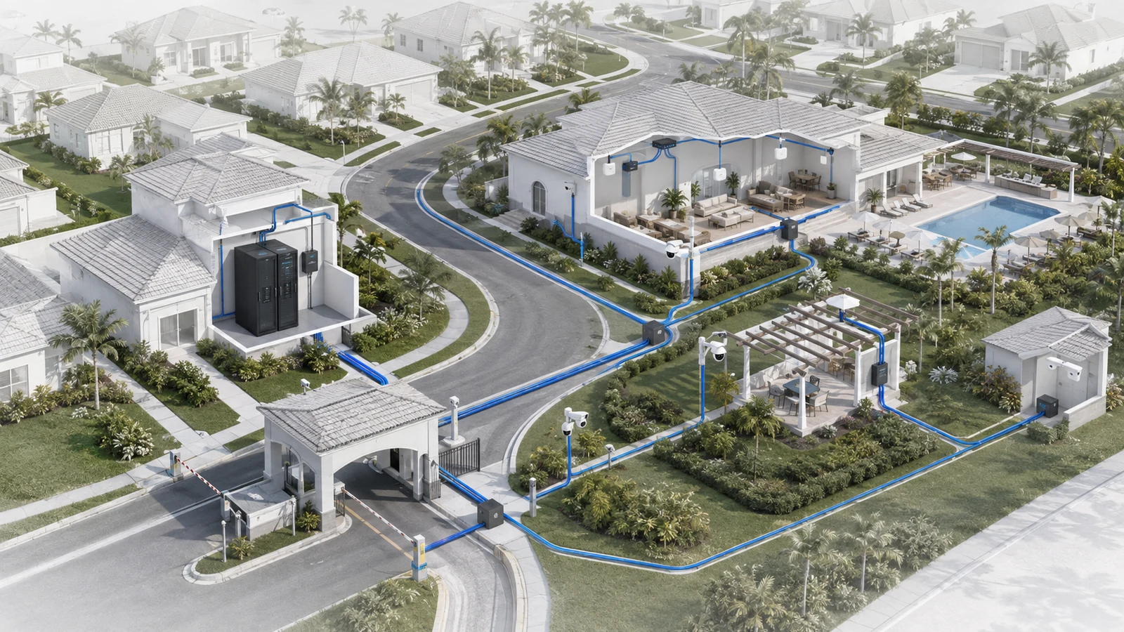
A community network is not simply a larger version of a home network. It may support administrative offices, gatehouses, clubhouses, pools, fitness centers, restaurants, surveillance cameras, access control, building automation, outdoor Wi-Fi, and connections between structures spread across a large property.
It must also remain understandable through board changes, management transitions, renovations, vendor turnover, and multiple generations of equipment. That makes ownership, documentation, physical pathways, and service boundaries just as important as switches and access points.
Not every community provides internet service to individual residences, and not every property needs an elaborate campus network. The architecture should reflect what the association actually owns and operates. The foundational principles, however, remain consistent: establish a controlled network edge, create dependable pathways between locations, separate systems according to risk and purpose, and document how the entire environment fits together.
01 Begin With the Community’s Actual Responsibilities
Before choosing equipment or drawing a network diagram, define which services belong to the association and which belong to residents, tenants, clubs, contractors, or independent service providers.
Community-owned infrastructure may include:
- Property-management and administrative connectivity
- Staff computers, printers, phones, and operational applications
- Gatehouses, entry systems, and visitor-management platforms
- Surveillance cameras and recording systems
- Door access, credential, and alarm systems
- Clubhouse, fitness center, restaurant, and event-space networks
- Resident and visitor Wi-Fi in common areas
- Irrigation, HVAC, lighting, pool, and building-control systems
- Maintenance facilities, marinas, sports areas, and other amenities
- Connectivity between association-owned buildings
Residential internet service may be completely separate, supplied through a bulk agreement, or partially integrated with shared infrastructure. Those arrangements materially change the architecture, support obligations, privacy considerations, and failure impact.
The first network document should therefore be a service-and-ownership map. It should show what the association controls, which vendors support each system, where the service boundaries sit, and who is responsible when something fails.
Without that clarity, a community can spend money improving equipment it does not own while overlooking infrastructure for which it remains responsible.
02 Understand the Main Infrastructure Layers
A useful community architecture can be understood as several connected layers. Smaller properties may combine multiple layers in one room or device. Larger communities may distribute them across several buildings.
| Infrastructure Layer | Role and Typical Components | Key Planning Question |
|---|---|---|
| Internet Edge |
Role: Connects association systems to external services. Components: ISP handoff, gateway, firewall, backup service, and remote-access controls. |
Which community services depend on internet availability? |
| Core and Backbone |
Role: Aggregates and transports traffic between major locations. Components: Core switching, routing, fiber links, and the main equipment room. |
How do buildings and service areas connect? |
| Building Distribution |
Role: Organizes connectivity within an individual structure or property zone. Components: Local switches, IDFs, patch panels, fiber uplinks, and UPS equipment. |
Which systems must remain operational within this location? |
| Access |
Role: Connects endpoint devices to the network. Components: Access switches, Ethernet drops, access points, cameras, and controllers. |
Where and how do devices physically connect? |
| Services and Security |
Role: Separates systems and controls permitted communication. Components: Network segments, firewall policies, management platforms, and logging. |
Which systems should be allowed to communicate? |
| Operations and Governance |
Role: Keeps the infrastructure supportable over time. Components: Diagrams, inventories, credentials, procedures, contracts, and ownership records. |
Can the next responsible team understand and operate the system? |
This layered model is not intended to force unnecessary complexity. It provides a way to assign responsibility and recognize dependencies. When every device is connected without a defined structure, troubleshooting becomes slower and changes become riskier.
03 Establish a Controlled Internet Edge
The internet edge is the boundary between association-operated systems and outside networks. It typically includes the service-provider handoff and a gateway or firewall that controls outbound, inbound, and remote-management traffic.
The correct internet design depends on the community’s operational requirements. A small association office may tolerate a temporary outage differently from a property where the internet connection supports gate access, payment systems, phones, cloud-managed cameras, or a busy clubhouse.
Planning questions should include:
- Which systems stop functioning when the primary internet service fails?
- Which systems continue locally but lose remote visibility?
- Does the property need a secondary connection?
- Will backup connectivity activate automatically or require intervention?
- Who receives service alerts and contacts the provider?
- How do vendors obtain authorized remote access?
- Which inbound services, if any, must be exposed externally?
A secondary internet connection does not automatically create resilience. The gateway must support the intended failover behavior, essential services must be tested over the alternate path, and staff must understand what functionality will and will not remain available.
The internet edge should also be treated separately from the internal backbone. Increasing the ISP speed will not correct an overloaded switch, damaged fiber, poor Wi-Fi design, or a failed connection between buildings.
04 Build the Core and Inter-Building Backbone
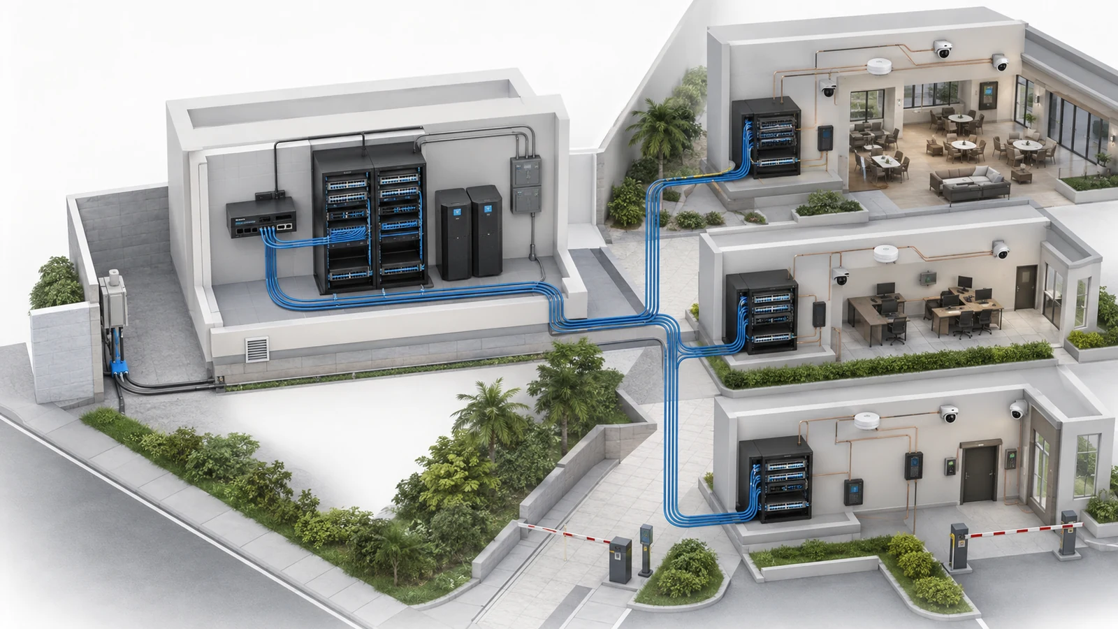
The core is the main aggregation point for the community’s shared network. In a larger property, it may reside in a primary equipment room commonly described as an MDF, or Main Distribution Frame. Smaller communities may use a secure wall-mounted cabinet or compact network room that performs the same practical role.
The core may connect:
- The internet gateway and firewall
- Administrative and management systems
- Building uplinks
- Surveillance recorders or supporting servers
- Clubhouse and amenity networks
- Gatehouses and perimeter systems
- Network-management and monitoring platforms
Connections from the core to other buildings or distant property areas form the backbone. Fiber is frequently preferred between buildings because it supports long pathways, high capacity, and electrical isolation between structures. The correct fiber type, strand count, pathway, termination method, and optics should be selected for the actual distances and expansion plan.
Copper Ethernet may remain appropriate within buildings and for some carefully evaluated short connections. Running copper between separate structures introduces distance, surge, grounding, and environmental considerations that should not be treated as a routine indoor cable installation. The dedicated guide to fiber versus copper between HOA buildings examines that decision in greater detail.
A backbone should be evaluated as a property asset rather than as an accessory to the switches installed today. Active equipment will be replaced more frequently than properly designed pathways and cabling.
05 Distribute Connectivity Within Each Building
A remote building may have an Intermediate Distribution Frame, or IDF, that connects back to the main network location. An IDF can be a dedicated room, cabinet, or rack containing the local patching, switching, power protection, and uplink equipment for that structure.
Not every building needs an elaborate IDF. The decision depends on the number of connected devices, cable distances, environmental conditions, service importance, and available space.
A properly planned building-distribution location should provide:
- A documented uplink to the community backbone
- Enough switch ports for current endpoints and reasonable growth
- An adequate PoE budget for access points, cameras, phones, and controllers
- Organized patching and cable labeling
- Clean, serviceable power and appropriate battery backup
- Ventilation and environmental conditions suitable for the equipment
- Physical security appropriate to the systems connected there
Local distribution also creates useful fault boundaries. A failed access switch in one building should not automatically disrupt every other location. However, that isolation depends on the architecture; moving equipment into separate rooms does not by itself create redundancy.
The balance between centralized and distributed infrastructure is explored in Centralized vs. Distributed Network Models in Gated Communities.
06 Connect Endpoints Through a Disciplined Access Layer
The access layer is where the infrastructure meets actual devices. It includes the switches, Ethernet cabling, wireless access points, cameras, door controllers, phones, workstations, televisions, audio systems, and building controls used throughout the property.
This layer often becomes disorganized because systems are installed at different times by different vendors. A camera contractor adds a switch, an access-control vendor installs another enclosure, an internet provider adds a gateway, and an AV company extends connectivity for an event space. Each component may work individually while the overall environment becomes difficult to understand.
A disciplined access layer uses:
- Documented cabling pathways and endpoint locations
- Consistent cable and port labels
- Managed switching where visibility or segmentation is required
- PoE capacity based on both individual devices and total switch power
- Wired connections for fixed, high-value infrastructure when practical
- Weather-appropriate equipment and enclosures in exposed areas
- Clear separation between association and vendor-owned equipment
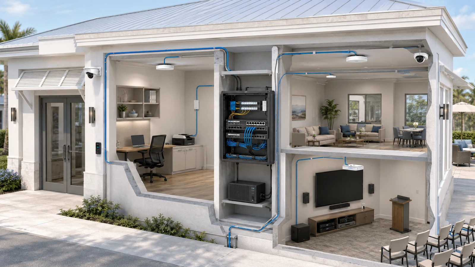
Clubhouses require particular attention because staff operations, resident Wi-Fi, events, audiovisual systems, cameras, access control, and food-service technology may occupy the same building. The guide to network infrastructure for clubhouses and shared community spaces addresses that mixed-use environment.
Outdoor Wi-Fi is another distinct access-layer discipline. Pools, courts, parks, marinas, entrance areas, and walking paths should be designed as intentional coverage zones rather than as accidental extensions of indoor access points. See the outdoor Wi-Fi strategy for residential communities for that planning process.
07 Define Service Boundaries and Network Segmentation
Community networks support multiple stakeholders and systems with different trust requirements. Administrative computers should not automatically share unrestricted access with guest devices, cameras, irrigation controllers, vendor equipment, and public Wi-Fi users.
Common logical service groups may include:
- Property management and administration
- Staff devices and operational applications
- Resident and visitor internet access
- Surveillance cameras and recording platforms
- Access control, gates, and visitor-management systems
- Building automation, HVAC, irrigation, lighting, and pool systems
- Restaurant, point-of-sale, or payment environments
- Audiovisual and event systems
- Vendor-managed devices and temporary service access
- Network-management interfaces
These groups do not necessarily require one network segment each. The appropriate design depends on risk, operational dependencies, vendor requirements, and the team’s ability to support the resulting policies.
Segmentation is commonly implemented with VLANs and firewall or routing rules. The important outcome is not the number of VLANs; it is whether communication between systems is explicitly understood and limited to what operations require.
For example, guest Wi-Fi generally needs internet access but should not provide a path to management computers or building controllers. Cameras may need to communicate with their recorder and approved management endpoints without being reachable from public or general-purpose networks.
Security boundaries should also exist operationally. Shared vendor credentials, undocumented remote access, and unknown cloud accounts can defeat an otherwise well-segmented technical design.
08 Protect the Physical Environment and Operational Continuity
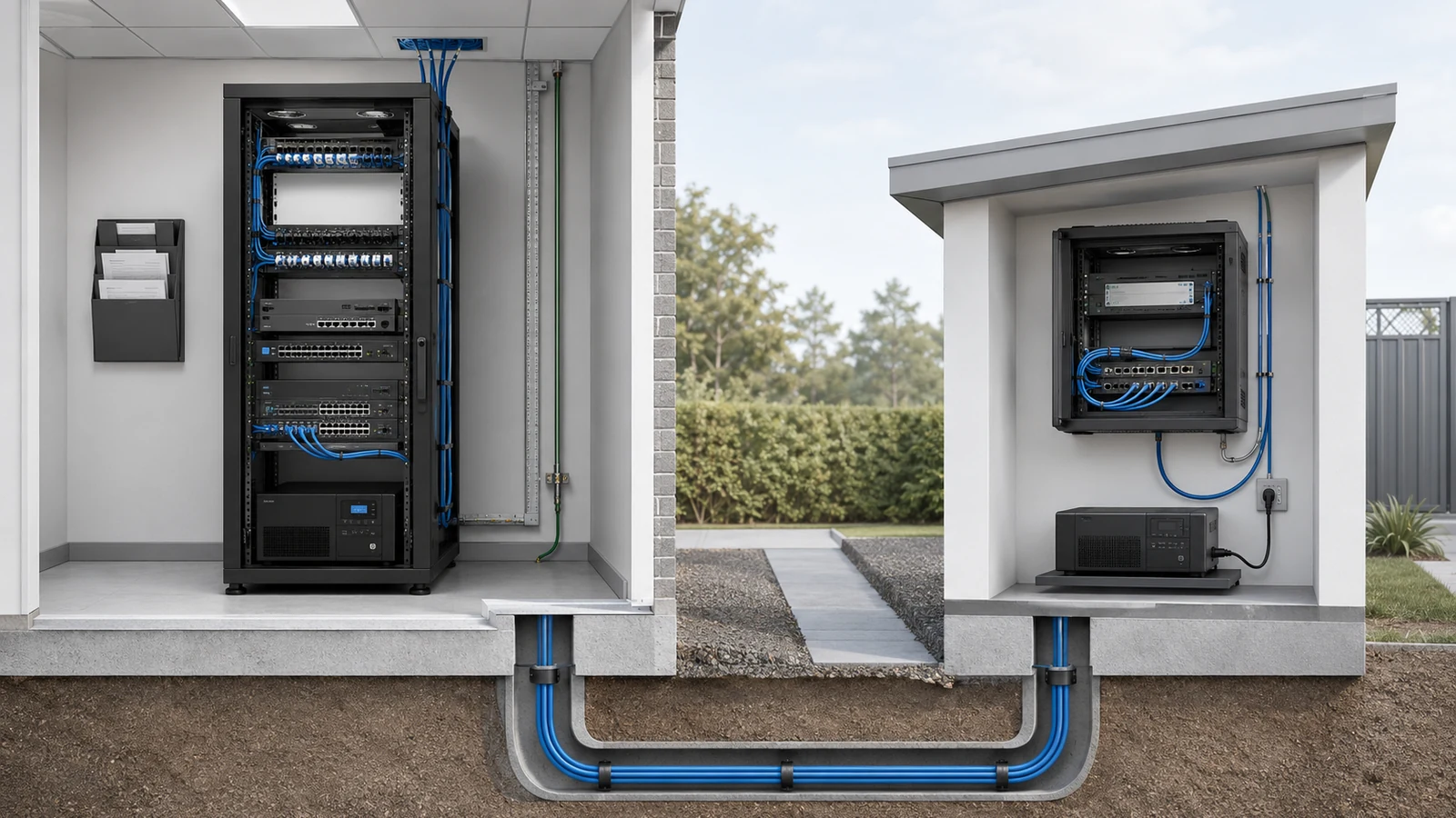
Network availability depends on more than logical architecture. Community equipment is often placed in rooms originally intended for storage, electrical service, maintenance, or low-voltage termination. Heat, moisture, dust, pests, unstable power, physical access, and accidental damage can become major sources of failure.
Every primary and secondary equipment location should be reviewed for:
- Dedicated and clearly identified electrical service
- UPS capacity aligned with the intended runtime and connected load
- Adequate airflow and temperature control
- Water exposure and plumbing located above or nearby
- Rack, cabinet, and equipment mounting security
- Cable entry, bend radius, strain relief, and organization
- Authorized physical access
- Environmental monitoring where operationally justified
Backup power expectations should be documented by service. Keeping a switch running does not guarantee that the ISP handoff, gate controller, camera recorder, access-control hardware, or remote cloud service will remain available. The entire dependency path must be considered.
Outdoor pathways require similar discipline. Conduit capacity, pull points, drainage, handholes, enclosure ratings, lightning exposure, grounding, surge protection, and future cable access should be addressed by appropriately qualified professionals.
09 Make Documentation and Governance Part of the Architecture
Community infrastructure regularly outlives board terms, management assignments, vendor contracts, and individual pieces of equipment. A technically strong design can still become fragile when no one knows how it was built or who controls it.
At minimum, the community should maintain:
- A high-level diagram showing buildings, backbone links, and major systems
- An inventory of gateways, switches, access points, recorders, controllers, and critical endpoints
- MDF, IDF, rack, patch-panel, and switch-port documentation
- ISP account, circuit, support, and service-boundary information
- Network segment and approved communication summaries
- Vendor ownership, support responsibility, and escalation contacts
- Secure administrative credential and account-ownership records
- Configuration-backup and recovery procedures
- Change records for important infrastructure modifications
- Renewal, warranty, licensing, and equipment-review dates
Documentation should be understandable at more than one level. Board members and property managers need a clear operational overview. Technical teams need enough detail to troubleshoot, maintain, and safely change the environment.
Network governance should also define who may approve changes, who can authorize vendor access, how incidents are escalated, and what records must be returned when a provider relationship ends.
Many recurring failures originate in missing ownership and documentation rather than in the equipment itself. The companion article on what HOAs commonly get wrong about shared network infrastructure examines those failure patterns more closely.
Community Network Infrastructure Review
- Define which technology services and physical assets the association owns.
- Document the boundary between association infrastructure and resident services.
- Identify the primary internet edge and every critical internet-dependent system.
- Map the MDF, IDFs, cabinets, racks, and major equipment locations.
- Document fiber, copper, wireless, and provider links between community areas.
- Confirm switch capacity, uplink capacity, and PoE requirements at each location.
- Separate public, administrative, security, building, and vendor systems according to risk.
- Review equipment rooms for power, UPS runtime, cooling, moisture, and physical access.
- Identify single points of failure and document their actual operational impact.
- Record vendor responsibilities, remote-access methods, accounts, and escalation paths.
- Maintain current diagrams, inventories, port records, configuration backups, and change history.
- Review the architecture before adding major amenities, buildings, cameras, access points, or control systems.
A community network should be understood as long-term property infrastructure. The internet gateway, switches, and access points will change, but the pathways, equipment locations, service boundaries, documentation, and ownership model determine whether future upgrades are orderly or disruptive.
The strongest community networks are not necessarily the most complicated. They are the ones in which every major system has a defined purpose, a suitable connection, an appropriate security boundary, a responsible owner, and a documented support path.
When those elements are planned together, the network becomes a stable foundation for administration, amenities, safety, resident services, and future property improvements.