
Introduction
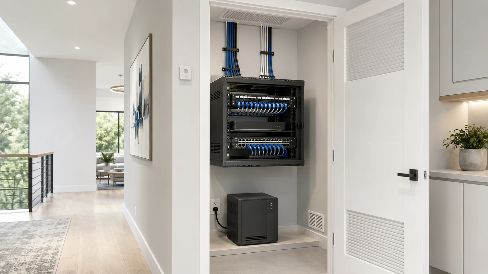
A home network closet is the location where the property’s communications infrastructure comes together. It may contain the internet handoff, gateway, patch panels, switches, video recorder, automation controllers, battery backup, and the terminations for Ethernet cables distributed throughout the home.
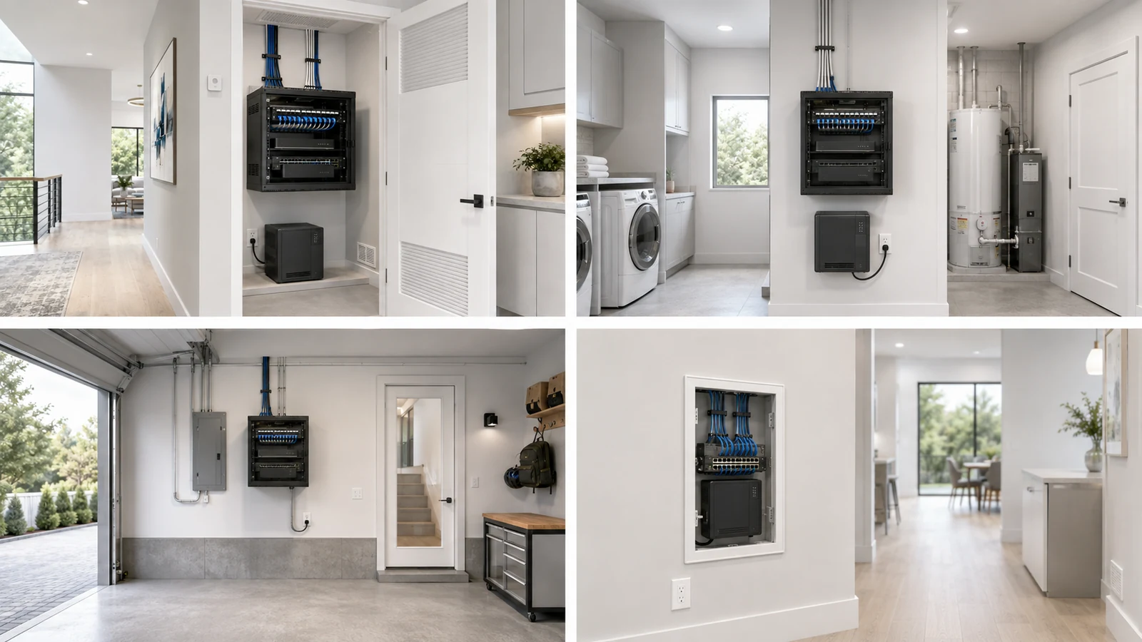
Despite the name, it does not have to be a conventional walk-in closet. It may be a dedicated technology room, a conditioned utility space, a wall-mounted cabinet, a structured wiring area, or a carefully planned section of another service room.
What matters is not the label on the room. The location must provide the space, environment, power, airflow, pathways, security, and working access required by the equipment it supports.
01 What Belongs in a Home Network Closet
The contents depend on the property. A modest home may need only a gateway, small switch, patching, and battery backup. A larger residence may also support multiple access points, security cameras, network storage, automation, audio distribution, and secondary equipment locations.
Common components include:
- Internet handoff: The modem, optical network terminal, or other service-provider equipment.
- Gateway or firewall: The device connecting the home network to the internet and enforcing routing and security policies.
- Network switch: The wired distribution layer for access points, cameras, computers, televisions, and other Ethernet devices.
- Patch panels: The organized termination point for permanent building cabling.
- Power over Ethernet: Switching or injectors that provide data and power to compatible devices.
- Video recorder: Local storage or processing for a camera system when used.
- Automation and control equipment: Bridges, controllers, hubs, and other property-technology devices.
- Uninterruptible power supply: Battery backup for selected critical equipment.
- Cable management and documentation: Labels, patch cords, diagrams, and service records.
Not every device needs to occupy the same enclosure. Large battery systems, audio amplifiers, storage servers, and other deep, heavy, noisy, or heat-producing equipment may justify separate placement even when they remain connected to the same network.
The closet should be designed around a documented equipment list rather than a generic photograph of an elaborate home rack.
02 Why Centralization Improves the Network
Without an intentional equipment location, network components tend to accumulate wherever the internet provider first installed service. The gateway may sit in one room, a switch in another, camera equipment on a shelf, and cable terminations inside an overcrowded panel.
Centralization provides:
- One understandable point for patching and distribution
- Easier troubleshooting and equipment replacement
- Centralized PoE for access points, cameras, and other devices
- Cleaner battery backup for critical network components
- Better labeling and documentation
- Improved control over physical access
- More predictable expansion
Centralization does not mean that every device must be forced into one small space. It means the system has a clear core and documented relationships between primary and secondary locations.
In a very large property, a main network room may feed a smaller secondary cabinet or switch in another section of the home. That can reduce difficult cable runs and support remote buildings or wings, provided the backbone between locations is designed correctly.
The broader architectural role of the gateway, switching, cabling, and wireless system is explained in the correct way to design Wi-Fi and wired infrastructure.
03 Choose the Location According to Risk and Access
The best network location is not always the geometric center of the house. Copper Ethernet distances are rarely the deciding limitation within an ordinary residence. Environmental stability, pathway access, electrical service, equipment clearances, and maintainability usually matter more.
A strong location is generally:
- Dry and protected from plumbing leaks or water intrusion
- Within conditioned or otherwise manufacturer-appropriate temperatures
- Accessible without moving stored household items
- Near useful cable pathways between floors and major sections of the property
- Large enough for safe installation and future service
- Close enough to the ISP handoff for a practical connection
- Supplied by properly planned electrical service
- Secure from children, guests, tenants, or unauthorized access when necessary
Avoid placing equipment directly beneath water heaters, plumbing manifolds, drain lines, air-conditioning equipment, or other likely sources of leakage. Laundry rooms, garages, and utility spaces are not automatically unsuitable, but humidity, temperature, dust, chemicals, vibration, water, and physical access must be evaluated honestly.
Noise also matters. Switches, recorders, servers, UPS units, and ventilation fans may produce a constant hum. A network location sharing a bedroom wall or sitting inside a quiet office can become irritating even when technically functional.
| Possible Location | Potential Advantages | Questions to Resolve |
|---|---|---|
| Dedicated interior closet | Controlled access, clean appearance, and potential proximity to vertical pathways | Is there adequate depth, ventilation, electrical service, and working clearance? |
| Conditioned utility room | Existing service access and space for wall-mounted equipment | Are water, vibration, dust, chemicals, and mechanical equipment safely separated? |
| Garage | Convenient ISP entry, exterior pathways, and freedom from living-space noise | Are heat, humidity, dust, pests, vehicle exposure, and physical security acceptable? |
| Laundry area | May contain structured cabling or central wall space | Can the equipment be protected from leaks, humidity, vibration, heat, and stored products? |
| Structured wiring panel | Compact, concealed, and often already connected to building cabling | Can it accommodate equipment depth, cable bend radius, power, ventilation, and expansion? |
| Dedicated technology room | Best control over space, racks, airflow, serviceability, and growth | Does the project’s scale justify the additional room and building systems? |
04 Size the Space From the Equipment Outward
There is no universal minimum width, depth, or rack-unit count for every home network closet. The required space depends on the equipment dimensions, cable count, mounting method, ventilation, power, door swing, service clearance, and expected growth.
Begin with the deepest and heaviest planned components. A shallow gateway and compact switch need far less room than a rack-mounted recorder, network storage appliance, large UPS, or audio system.
The layout should provide:
- Clearance for the deepest device and its rear connections
- Space for Ethernet bend radius and patch cords
- Access to both power and data connections
- Room to remove or replace individual components
- Safe support for the total equipment weight
- Air space around heat-producing devices
- Reasonable working room in front of the equipment
- Capacity for likely additions without rebuilding the location
Do not select an enclosure before checking actual equipment dimensions. Rack-mount width does not guarantee that a cabinet has sufficient usable depth, and a nominal wall-panel size does not reveal how much space remains after cable, power, and mounting hardware are installed.
Growth capacity should be reasonable rather than unlimited. Leaving some unused patch-panel ports, switch capacity, power headroom, and physical space is sensible. Doubling every component automatically may waste space and budget without solving a defined need.
05 Decide How the Equipment Will Be Mounted
The network closet describes the location. The rack, cabinet, backboard, shelf, or structured panel describes how equipment is supported within that location.
Common approaches include:
- A structured media panel for compact terminations and small devices
- A wall-mounted open-frame rack
- An enclosed wall cabinet
- A floor-standing rack for deeper or heavier systems
- A plywood or purpose-built backboard with approved shelves and mounting hardware
- A hybrid arrangement using a structured panel for cabling and a nearby rack for active equipment
The right choice depends on cable volume, device depth, weight, heat, appearance, accessibility, and expansion. A rack is not automatically required for a professional residential network, and a structured panel is not automatically inadequate.
The separate guide to home network racks versus structured wiring panels provides the complete enclosure comparison.
06 Plan Cabling and Serviceability Together
Permanent Ethernet cables should enter the network location through organized pathways and terminate on patch panels or compatible keystone hardware. Short patch cords then connect the required ports to the network switch.
A maintainable layout normally includes:
- Clearly separated permanent cabling and removable patch cords
- Labels at both ends of every permanent run
- Logical patch-panel and switch-port organization
- Appropriate cable support and bend radius
- Reasonable service loops
- Accessible uplink, ISP, and power connections
- Documented secondary switches or equipment locations
Avoid routing cables so tightly that one device cannot be removed without disconnecting several others. Velcro-style reusable ties are generally more serviceable than overtightened permanent ties around changing patch-cord bundles.
The location should also connect cleanly to the property’s vertical and horizontal cable pathways. New construction may provide conduits or open framing. A retrofit may depend on attic access, chases, soffits, closets, or discreet surface pathways.
The detailed residential Ethernet cabling strategy explains cable selection, home-run termination, conduit, testing, and documentation.
07 Provide Power According to the Actual Load
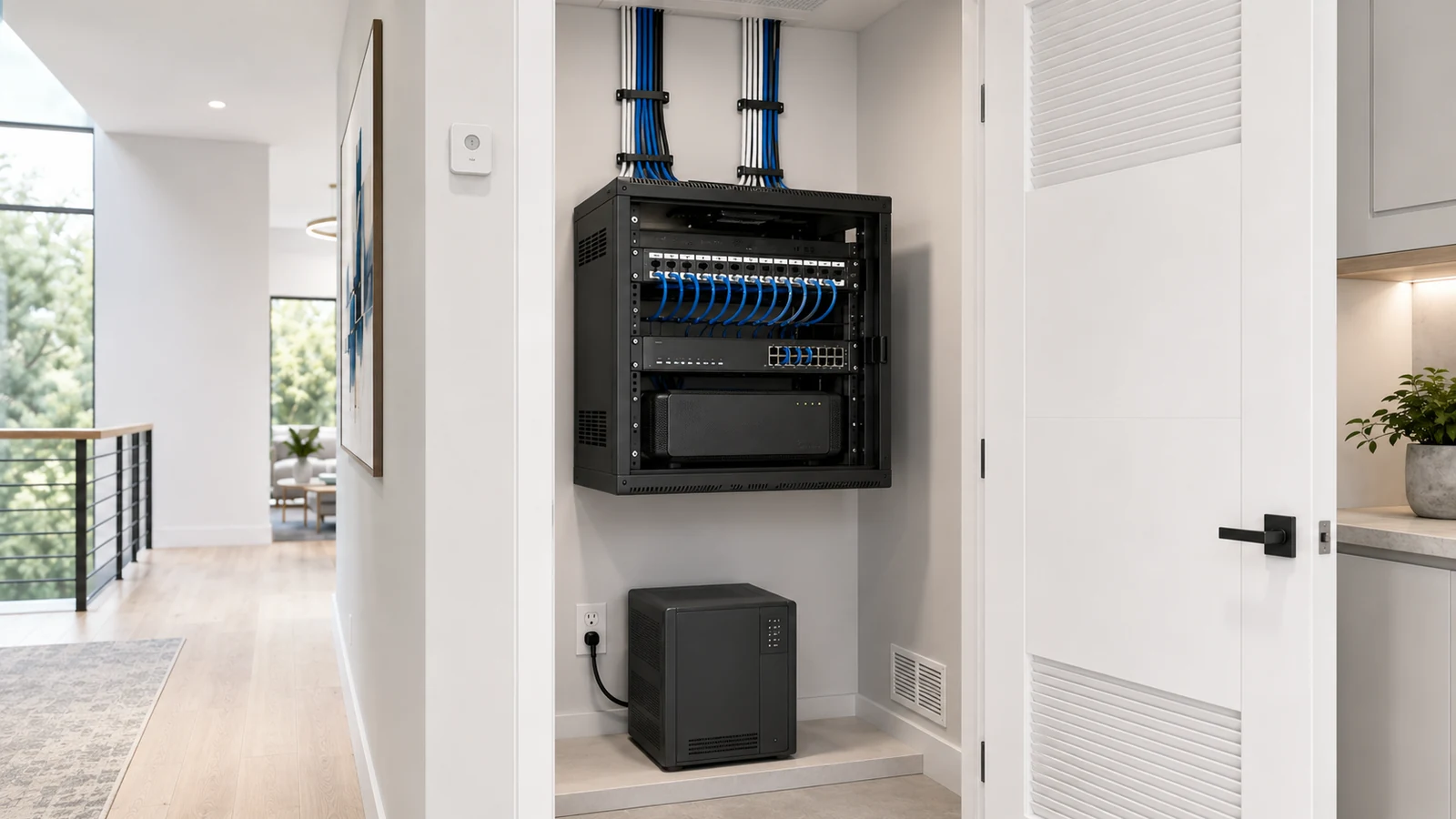
Network equipment operates continuously, making power planning an essential part of the closet rather than a last-minute power-strip decision.
Document the electrical load of:
- The gateway or firewall
- Network switches
- PoE-powered access points, cameras, and other endpoints
- The ISP modem or optical network terminal
- Video recorders and storage drives
- Network-attached storage
- Automation controllers
- Ventilation equipment
Electrical service should be installed and protected according to applicable requirements. Avoid extension cords and improvised multi-adapter arrangements as permanent infrastructure.
A UPS can keep selected equipment operating through brief power interruptions and provide orderly shutdown time for devices that need it. UPS selection should be based on the measured or calculated load, desired runtime, power characteristics, battery service requirements, and criticality—not a universal VA recommendation.
Decide what must remain available during an outage. Keeping the gateway and core switch online may preserve local networking, cameras, and internet service if the provider remains operational. Powering a large PoE camera system or storage server for extended runtime requires substantially more battery capacity.
Battery backup also produces heat, occupies space, adds weight, and requires eventual maintenance. Position it so batteries can be inspected and replaced without dismantling the network.
08 Control Heat Before It Becomes a Reliability Problem
Gateways, switches, PoE power supplies, recorders, storage devices, and UPS units convert part of their electrical load into heat. A closet that feels acceptable when empty may become considerably warmer after equipment is installed and the door is closed.
Thermal planning should consider:
- The combined equipment load
- Manufacturer operating-temperature requirements
- Air intake and exhaust locations on each device
- Clearance around passive and actively cooled equipment
- Whether the door and enclosure restrict natural airflow
- Ambient conditions during the hottest part of the year
- Additional heat from PoE loads, recorders, storage, and battery charging
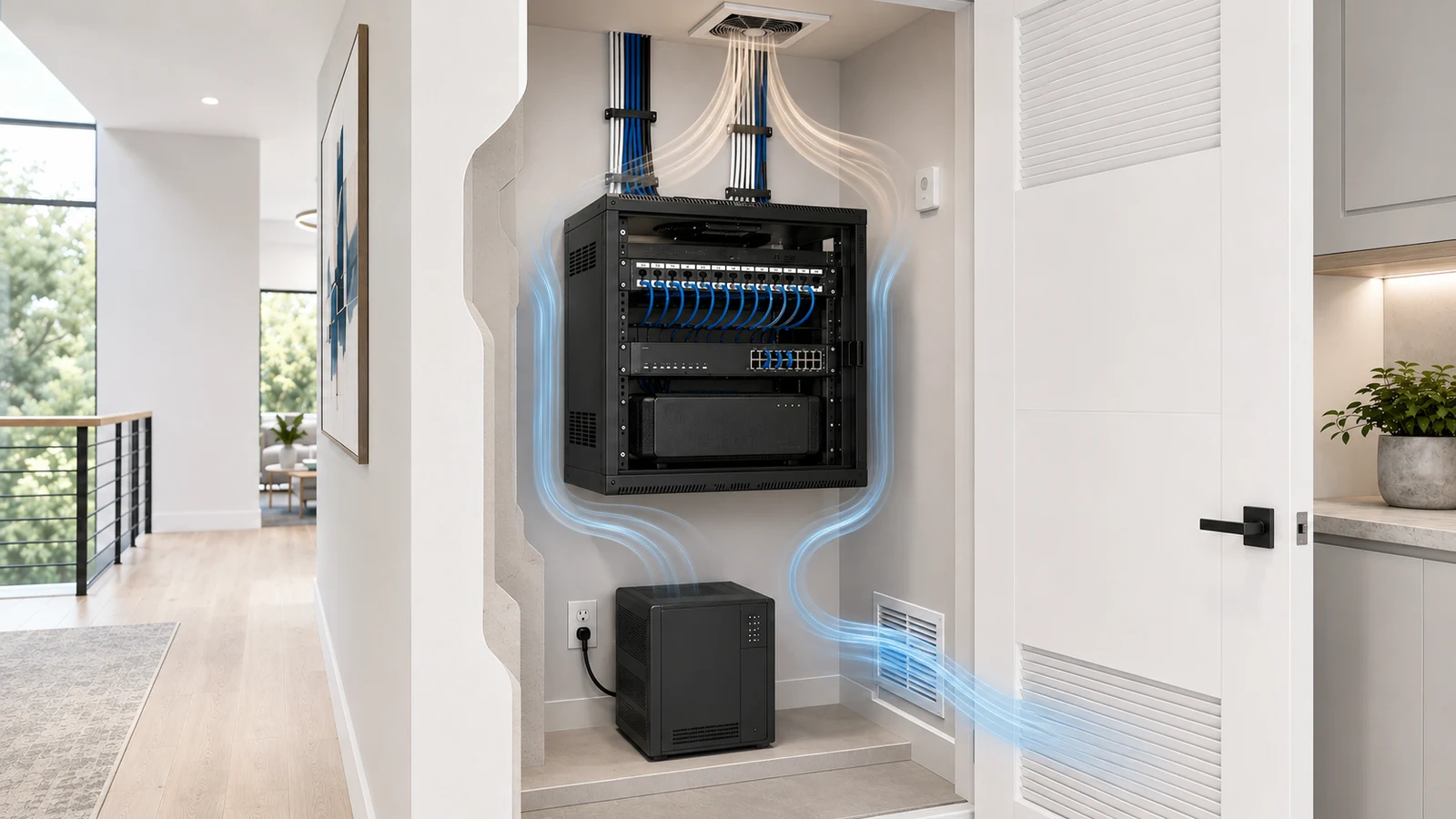
Possible solutions include passive door grilles, transfer openings, conditioned-air strategies, thermostatically controlled fans, or dedicated cooling for a large equipment room. Any modification must respect fire, smoke, acoustic, and building-system requirements.
Fans should move air through a defined path rather than circulate the same hot air inside a sealed cabinet. Intake and exhaust openings should not be blocked by shelves, stored boxes, clothing, or insulation.
Monitor the finished space before assuming the design is adequate. A simple temperature sensor can reveal conditions during normal use and after power or cooling changes.
09 Protect Access and Document the System
The network closet may control internet access, cameras, smart-home systems, work connectivity, and other property services. Physical access should match the importance of those systems.
Security considerations may include:
- A door, cabinet, or enclosure that limits casual tampering
- Controlled access in rental, guest, staff, or shared-property environments
- Protection of reset buttons, removable storage, and exposed patch cords
- Remote administration that does not require leaving the room unsecured
- Emergency access for an authorized homeowner or service provider
Do not make the system so inaccessible that routine inspection becomes unlikely. Security and serviceability must coexist.
Keep a current network record containing:
- A simple topology diagram
- Patch-panel and outlet identifiers
- Switch-port assignments
- ISP equipment and support information
- UPS model, load, and battery-service date
- Equipment model and serial information
- Configuration-backup locations
- Important maintenance and replacement dates
Sensitive credentials should be stored securely rather than displayed inside the closet. The physical documentation should help someone understand the system without exposing passwords or recovery information.
10 Final Home Network Closet Blueprint
Home Network Closet Readiness Checklist
- List every device expected to occupy the location.
- Confirm the depth, weight, clearance, and airflow requirements of the largest equipment.
- Select a dry location protected from plumbing and environmental hazards.
- Review heat, humidity, dust, vibration, pests, and seasonal conditions.
- Check whether fan, recorder, and UPS noise will affect adjacent rooms.
- Confirm practical pathways to the ISP handoff, floors, access points, cameras, and exterior systems.
- Provide electrical service based on the calculated equipment load.
- Size battery backup according to critical devices and desired runtime.
- Select a rack, panel, cabinet, or backboard based on actual equipment and cable requirements.
- Terminate permanent cabling on organized, labeled patching hardware.
- Keep connections and equipment accessible for testing and replacement.
- Provide a defined ventilation or cooling approach.
- Prevent the technology space from becoming household storage.
- Control physical access appropriately.
- Document the topology, ports, equipment, backup locations, and maintenance dates.
- Leave reasonable physical, electrical, switching, and patch-panel capacity for growth.
A home network closet does not need to resemble a commercial data center. It needs to support the property’s actual infrastructure safely, clearly, and maintainably.
Choose the environment before choosing the enclosure. Size the location from the equipment outward. Provide dependable power and an honest thermal plan. Organize the cabling so future service does not require reverse-engineering the house.
When these fundamentals are correct, the network closet becomes what it should be: a quiet, dependable foundation for connectivity throughout the property.