
Introduction
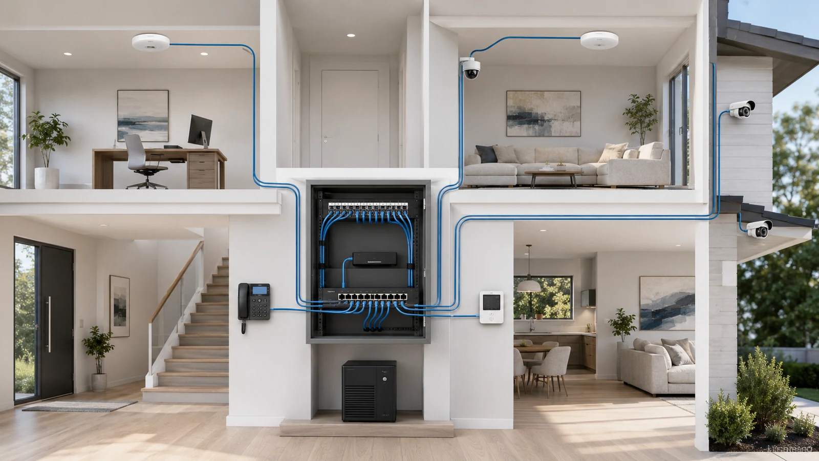
Power over Ethernet allows one network cable to carry both data and electrical power to a compatible device. That makes it possible to install a wireless access point on a ceiling, a security camera under an eave, or a phone on a desk without placing a separate electrical outlet beside each device.
PoE is convenient, but its real value is architectural. Power can originate from a central network location, critical devices can share battery backup, and individual connections can be monitored or restarted when the switch supports those functions.
Successful PoE design requires more than counting ports. The switch or injector must support the device’s power standard, the total power budget must cover the combined load, and the cabling must be appropriate for the installation.
01 What Power over Ethernet Actually Does
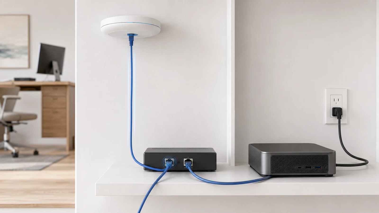
A conventional Ethernet connection carries network data. A PoE connection adds low-voltage power to the same balanced cable while preserving Ethernet communication.
A standardized PoE connection contains two primary roles:
- Power sourcing equipment: The switch or injector that provides power, commonly called the PSE.
- Powered device: The access point, camera, phone, or other endpoint receiving power, commonly called the PD.
With standards-based active PoE, the power source detects and classifies a compatible device before applying operational power. The connected endpoint then draws power according to the negotiated capability and its actual demand.
This allows ordinary non-PoE Ethernet devices to connect safely to standards-compliant PoE switch ports. The port does not simply force full power onto every connected cable.
Passive or proprietary power systems are different. They may place voltage on conductors without the same standardized negotiation and can have different voltage, wiring, or compatibility requirements. Passive PoE should never be assumed compatible merely because the connector looks like Ethernet.
02 Understand PoE, PoE+, and PoE++
PoE standards support different maximum power levels. More demanding access points, pan-tilt-zoom cameras, displays, lighting, and building devices may require a higher class than a basic phone or fixed camera.
The values commonly associated with each standard describe the maximum power available from the power-sourcing equipment. The amount guaranteed at the powered device is lower because some energy is lost along the cabling and connections.
| PoE Standard | Maximum PSE Power | Typical Device Considerations |
|---|---|---|
| IEEE 802.3af PoE / Type 1 |
Up to 15.4 watts from the sourcing port | Lower-power phones, simple cameras, sensors, and compatible access points |
| IEEE 802.3at PoE+ / Type 2 |
Up to 30 watts from the sourcing port | Many modern access points, cameras, intercoms, and other moderate-power devices |
| IEEE 802.3bt PoE++ / Type 3 |
Up to 60 watts from the sourcing port | Higher-power access points, advanced cameras, displays, and specialized devices |
| IEEE 802.3bt PoE++ / Type 4 |
Up to 90 watts from the sourcing port | High-power building devices and specialized equipment designed for Type 4 service |
A higher-capacity PoE port does not normally force its maximum power into a lower-power standardized device. The source and device negotiate the supported level. However, the switch, injector, cabling, intermediate connections, and endpoint must all be compatible with the required mode.
Product descriptions sometimes use terms such as PoE++, high-power PoE, or specific wattage ratings inconsistently. Verify the underlying IEEE type, supported power classes, and power available at the endpoint rather than relying only on the marketing name.
03 Where PoE Creates the Most Value at Home
PoE is most useful for infrastructure devices that need both Ethernet and dependable power in locations where ordinary outlets would be inconvenient.
Wireless access points: PoE allows access points to be installed on ceilings, walls, or other planned coverage locations without nearby electrical adapters. Their power and wired backhaul return to the central network.
Security cameras: One cable can provide a stable network connection and centralized power. Cameras can remain operational from the network UPS when the switch and recording system are backed up appropriately.
VoIP phones and intercoms: Desk phones, door stations, and compatible intercom devices can receive power and data from the same switch.
Door and access systems: Some readers, controllers, locks, and related devices support PoE or higher-power PoE variants. Life-safety, egress, code, and manufacturer requirements must take priority in these applications.
Smart-home and building devices: Touch panels, controllers, sensors, clocks, lighting components, and compact computers may use PoE when designed for it.
Remote network equipment: Certain small switches, bridges, and converters can be powered through Ethernet, although pass-through power and total downstream demand require careful calculation.
PoE is not automatically necessary for televisions, desktop computers, appliances, or every fixed device. Use it where centralized low-voltage power genuinely simplifies the installation or improves continuity.
This role fits into the larger Wi-Fi and wired infrastructure architecture used throughout a structured home network.
04 Choose Between a PoE Switch and an Injector
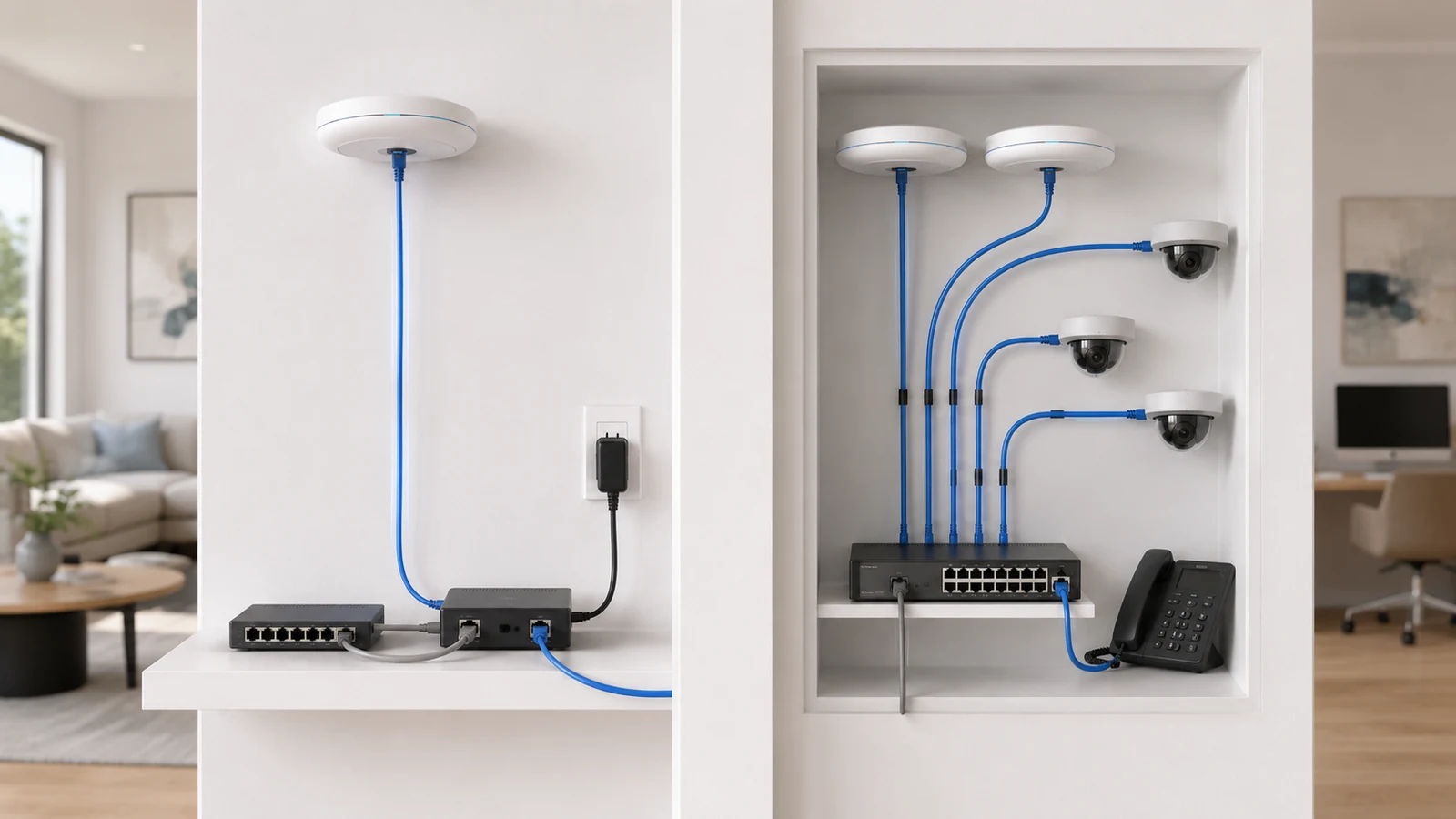
A PoE switch combines Ethernet switching and power delivery across one or more ports. A PoE injector adds power to an Ethernet connection between a non-PoE switch and one compatible powered device.
An injector can be the right solution when:
- Only one device requires PoE.
- The existing switch otherwise meets the network’s needs.
- A temporary or transitional installation is being built.
- A device requires a power level not provided by the current switch.
- Replacing the primary switch would be disproportionate to the requirement.
A PoE switch is usually cleaner when:
- Several access points or cameras require power.
- Centralized battery backup is important.
- The design needs organized patching and fewer power adapters.
- Remote power control or monitoring would be useful.
- The network is expected to expand.
Injectors are not technically inferior. They become inconvenient when several units create a dense collection of adapters, electrical cords, heat sources, and undocumented power paths.
If injectors are used, label which device each one powers and document its voltage, standard, and maximum output. This is especially important when standards-based and proprietary equipment coexist.
05 Separate Per-Port Power From Total PoE Budget
A PoE switch has two different capacity limits:
- Per-port capability: The maximum standard and power level an individual port can provide.
- Total PoE budget: The combined amount of power available across all powered ports.
A switch may advertise many PoE-capable ports while lacking enough total budget to operate all of them at their maximum potential simultaneously.
Consider a simplified design with:
- Three access points requiring up to 21 watts each
- Six cameras requiring up to 9 watts each
- One intercom requiring up to 12 watts
The planned maximum demand would be:
- Access points: 3 × 21 watts = 63 watts
- Cameras: 6 × 9 watts = 54 watts
- Intercom: 1 × 12 watts = 12 watts
- Combined planned demand: 129 watts
A switch with ten PoE ports but only a 90-watt total budget would be undersized for that documented maximum load. A model with suitable per-port support and a budget comfortably above 129 watts would provide a more appropriate starting point.
Do not size the system from ordinary observed consumption alone. Some devices draw more during startup, infrared illumination, heater operation, radio activity, motor movement, USB use, or other peak conditions.
06 Decide Whether Managed PoE Features Are Useful
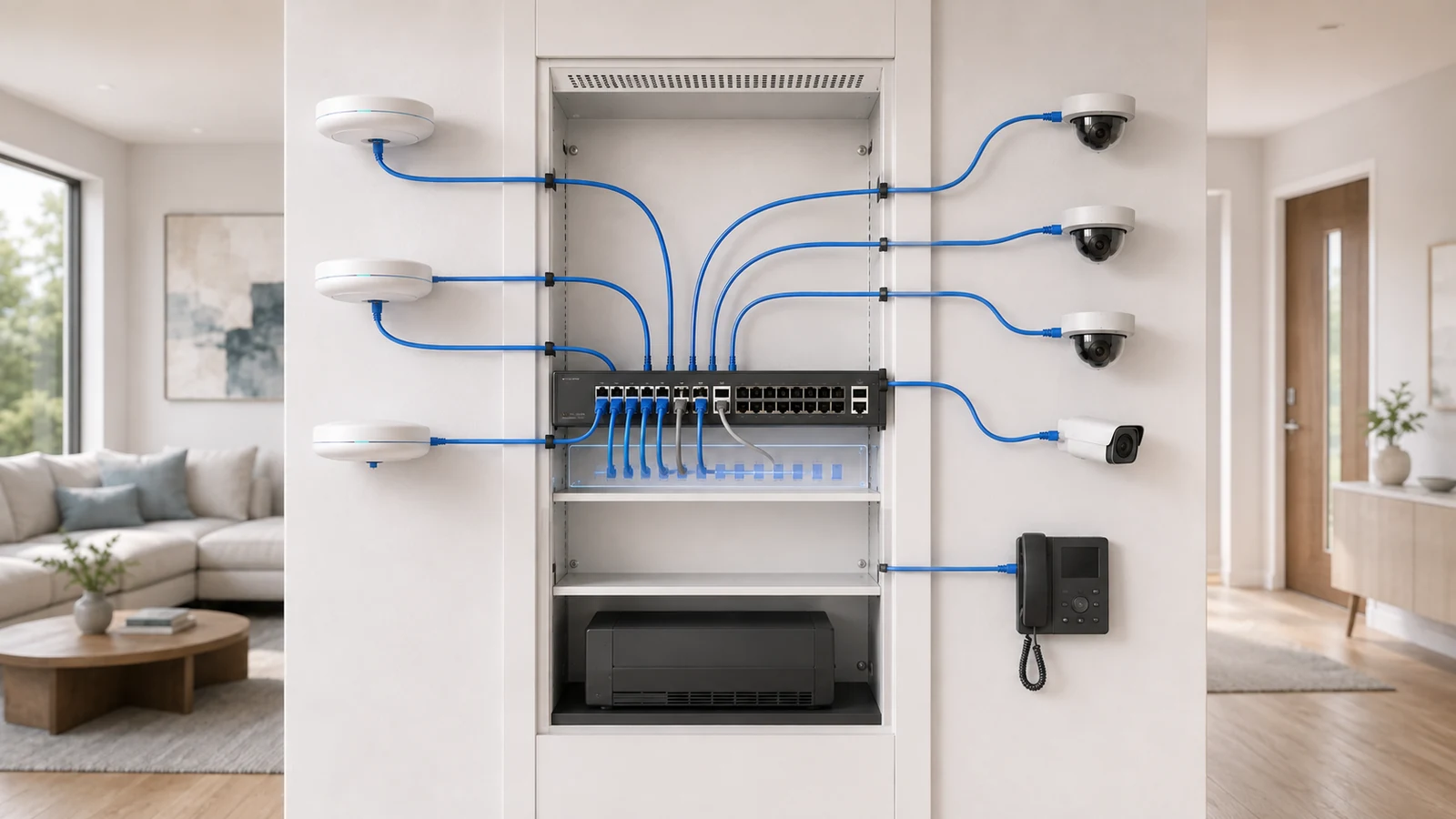
PoE can operate on unmanaged, smart-managed, or fully managed switches. Management is not required simply to deliver standardized power.
A managed PoE switch may add:
- Per-port power consumption
- Remote PoE disable and restart
- Alerts when a powered device disconnects
- Port scheduling on supported systems
- Priority behavior when the power budget is constrained
- VLAN assignment and traffic visibility
- Centralized administration with gateways and access points
Remote power cycling is particularly useful for ceiling access points, exterior cameras, and other devices that are difficult to reach physically. It should not substitute for diagnosing a device that requires repeated restarts.
An unmanaged PoE switch may be entirely appropriate when the network uses one ordinary segment and no port-level control or monitoring is needed. Review whether a managed switch makes sense at home before paying for features the system will not use.
07 Cabling Quality Affects Data and Power
PoE depends on the complete Ethernet channel: permanent cable, patch panels, keystone jacks, connectors, patch cords, and terminations. Poor materials or workmanship can affect both network communication and power delivery.
Important considerations include:
- Standards-compliant solid-copper cable for permanent runs
- The correct cable category and environmental listing
- Compatible patch panels, jacks, and patch cords
- Correct termination of all conductors
- Appropriate channel length
- Cable-bundle size and ambient temperature
- Protection from moisture, ultraviolet exposure, and physical damage
- Testing after installation
Power creates heat in the conductors. The effect becomes more important with higher-power devices, long runs, warm environments, and large cable bundles. Cable construction, conductor size, pathway conditions, and bundling should be evaluated for demanding installations.
Copper-clad aluminum cable should not be treated as equivalent to properly specified solid-copper communications cable, particularly where PoE load and installation reliability matter.
Exterior cameras and access points also require suitable cable, pathway, environmental protection, and surge planning. PoE does not remove the risks associated with outdoor copper connections.
The complete infrastructure considerations are covered in the Ethernet cabling strategy for modern homes.
08 Centralized Power Changes Backup and Failure Planning
One of PoE’s strongest advantages is the ability to support several remote devices from a centrally protected power source. If the gateway, PoE switch, internet handoff, and recording system connect to a suitable UPS, access points and cameras may continue operating during a brief power interruption.
UPS planning must include the complete load:
- The switch’s own consumption
- Power delivered to all PoE devices
- The gateway or firewall
- The modem or optical network terminal
- The camera recorder and storage drives
- Other critical controllers
A UPS that provides substantial runtime for an unloaded switch may deliver much less once it powers several access points, cameras, and a recorder. Runtime should be evaluated using the expected combined load and the critical services that must remain available.
Centralization also creates a shared failure domain. If one PoE switch powers every access point and camera, failure of that switch or its power source can affect all of them simultaneously.
More demanding properties may divide critical devices across switches, preserve spare ports and replacement equipment, or separate camera and wireless infrastructure. Most homes do not require extensive redundancy, but the consequences of a central failure should be understood.
The switch and UPS also generate heat and require service access. Place them in a properly planned home network closet rather than inside an enclosure selected only because the devices physically fit.
09 Avoid the Most Common PoE Planning Mistakes
Matching only the connector: An RJ45 connection does not prove that the device and power source use compatible standards or voltage.
Counting ports but ignoring budget: A switch may have enough physical ports while lacking enough total power.
Checking average instead of maximum demand: Cameras, access points, and other devices may draw more power during specific operating conditions.
Assuming every PoE port is identical: Some switches provide different power capabilities on different groups of ports.
Using undocumented injectors: Unlabeled adapters make future replacement and troubleshooting risky, particularly when passive power is involved.
Ignoring cable and connections: Damaged conductors, poor terminations, unsuitable patch cords, and excessive channel length affect power delivery.
Overlooking heat: High PoE loads increase switch and cable heat, especially in sealed panels and warm equipment spaces.
Forgetting backup load: UPS runtime must account for powered endpoints, not only the switch chassis.
Providing no headroom: A design operating continuously at its published limit has little flexibility for device peaks or future additions.
PoE Planning Checklist
- List every device that will receive power through Ethernet.
- Verify the exact PoE standard and maximum demand of each device.
- Confirm that each switch or injector port supports the required standard.
- Separate standards-based active PoE from passive or proprietary power systems.
- Add the maximum device requirements to calculate the planned total load.
- Leave reasonable headroom within the switch’s total PoE budget.
- Check whether different switch ports provide different power levels.
- Decide whether remote monitoring, power cycling, or VLAN support is needed.
- Use appropriate solid-copper permanent cabling and compatible connectivity.
- Evaluate cable length, bundles, ambient temperature, and equipment ventilation.
- Use suitable materials and protection for exterior connections.
- Include all powered endpoints when estimating UPS runtime.
- Document switch ports, injectors, device requirements, and power assignments.
- Consider the impact of a central switch or power failure.
PoE is one of the most useful building blocks in a structured home network. It places access points and cameras where they function best, reduces scattered power adapters, and allows critical infrastructure to share centralized monitoring and battery backup.
Its simplicity at the endpoint depends on good planning at the core. Match the standard, verify the budget, use appropriate cabling, manage heat, and document every powered connection.
When those details are handled correctly, one Ethernet cable becomes a clean, dependable path for both connectivity and power.