
Introduction
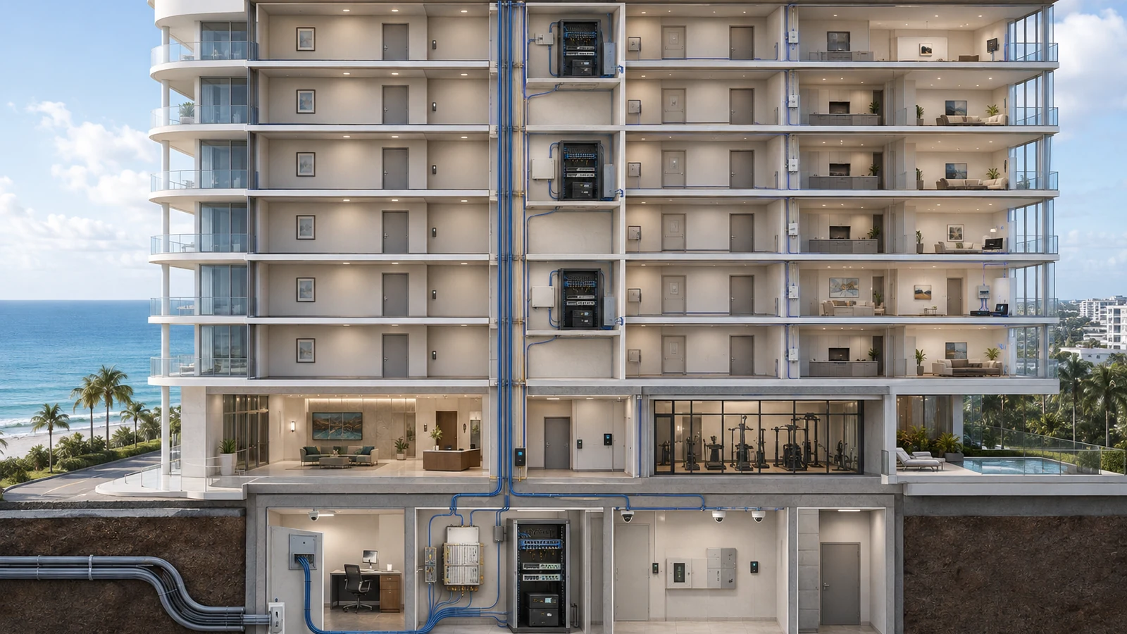
A high-rise residential network is not simply a large router serving many apartments. It is a vertical infrastructure system built around carrier entry points, telecommunications rooms, riser pathways, floor distribution, residential service boundaries, shared amenities, security systems, and building operations.
Some parts of that system may belong to an internet provider. Others may belong to the condominium association, building owner, developer, management company, or specialized technology vendors. Individual residents may purchase their own service and manage their own in-unit networks, while the building separately operates cameras, access control, offices, amenity Wi-Fi, and building systems.
Understanding those boundaries is the foundation of good MDU planning. Without them, network upgrades become difficult to scope, vendor responsibilities overlap, and one project may unintentionally depend on infrastructure controlled by someone else.
01 Start With Ownership and Service Boundaries
Before drawing a network diagram, determine which organization owns and operates each service.
A high-rise property may contain:
- Provider-owned internet infrastructure delivering service to residential units
- Building-owned internet service for administration and staff
- Association-managed Wi-Fi in lobbies, lounges, pools, or other amenities
- Surveillance cameras and recording platforms
- Door, garage, elevator-destination, and amenity-access systems
- Building automation, HVAC, lighting, irrigation, and monitoring systems
- VoIP, intercom, audiovisual, and digital-signage systems
- Resident-owned routers, access points, and connected devices inside units
- Cellular, public-safety, and other specialized communications infrastructure
These systems may share telecommunications rooms, risers, conduit, fiber pathways, racks, power, or support vendors without sharing the same network.
A useful ownership record should identify:
- The asset owner
- The service operator
- The administrative-account owner
- The physical demarcation point
- The responsible support provider
- The party authorized to approve changes
- The documents and configurations the building retains
Provider service boundaries deserve particular attention. An association may own the pathway and telecommunications rooms while the carrier owns the active equipment. Another provider may control the entire vertical distribution system. Those arrangements affect upgrades, competition, maintenance, and future transitions.
02 Understand the Building’s Network Layers
Although individual properties differ, most high-rise infrastructure can be understood through a set of connected layers.
| Infrastructure Layer | Role and Typical Components | Primary Planning Question |
|---|---|---|
| Carrier Entry and Demarcation | Brings external telecommunications services into the property through provider handoffs, entrance facilities, and demarcation equipment | Where does provider responsibility end and building responsibility begin? |
| Main Distribution | Houses primary fiber termination, core switching, gateways, provider equipment, management systems, and backbone aggregation where applicable | Does the main room provide suitable capacity, power, environment, security, and access? |
| Vertical Backbone | Connects the main distribution location to floors and building zones through fiber, riser pathways, patching, and termination points | Can the riser support current services, restoration, and reasonable future change? |
| Floor Distribution | Uses IDFs, cabinets, switches, splitters, patch panels, or provider equipment to distribute service across one or several floors | Are endpoints within supported distance and are local systems serviceable? |
| Access and Horizontal Cabling | Connects residential demarcations, common-area access points, cameras, controllers, offices, and other endpoints | Which devices connect locally, and who owns each final connection? |
| Services and Security | Separates resident, staff, public, surveillance, access-control, building, and management systems according to purpose and risk | Which systems may communicate, and where are those rules enforced? |
| Operations and Governance | Maintains accounts, diagrams, inventories, contracts, configurations, access records, support procedures, and change control | Can the property understand, operate, and transition its infrastructure? |
Smaller buildings may combine several layers in one telecommunications room. Large towers may distribute them across multiple risers, wings, mechanical levels, or groups of floors.
The purpose of the layered model is not to impose unnecessary complexity. It is to make dependencies and responsibilities visible.
03 Carrier Entry and the Main Distribution Frame
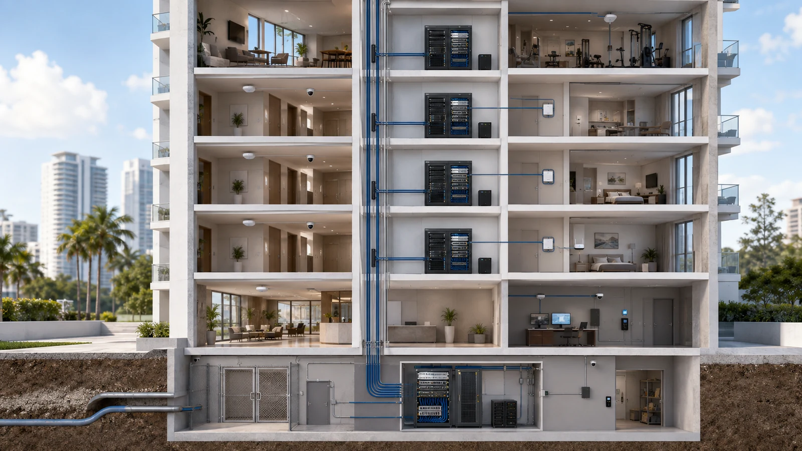
External telecommunications services enter the property through an entrance facility or carrier demarcation area. Depending on the building, multiple providers may use separate pathways and equipment or share portions of the entrance infrastructure.
The main distribution location—often called the MDF—may contain:
- Carrier fiber and demarcation equipment
- Building internet gateways and firewalls
- Core or aggregation switches
- Fiber-distribution frames and patch panels
- Network-management platforms
- Security recorders or supporting servers
- Building-system interfaces
- UPS and power-distribution equipment
Not every component belongs in one rack or on one network. Provider equipment, association systems, security infrastructure, and building automation may require separate enclosures, responsibilities, or access controls.
The room itself should be treated as critical property infrastructure. Planning should address:
- Authorized physical access
- Rack and wall space
- Electrical capacity and circuit identification
- UPS expectations and connected load
- Cooling, airflow, moisture, dust, and plumbing exposure
- Fiber and copper cable management
- Provider working space and demarcation boundaries
- Expansion and equipment-replacement access
A second internet service or redundant core switch cannot correct a vulnerable room, shared unprotected power, or one damaged pathway carrying every service.
04 The Vertical Backbone and Riser System
The vertical backbone connects the building’s primary distribution location to upper floors, remote wings, rooftop amenities, parking levels, and other telecommunications zones.
Fiber is commonly used because it supports long vertical pathways, substantial capacity, and electrical isolation between connected network interfaces when the optical path is properly designed. The exact fiber type, strand count, construction, termination, and optical equipment should follow the building’s service and ownership model.
The riser system includes more than cable. It may involve:
- Dedicated telecommunications pathways
- Riser-rated or otherwise appropriate cable construction
- Sleeves, conduit, trays, and accessible pull locations
- Firestopping and building penetrations
- Fiber-distribution frames and floor terminations
- Spare strands and restoration options
- Identification and as-built pathway records
Pathway access is often more difficult to change than active network equipment. A building can replace switches and optical interfaces, but an inaccessible or fully occupied riser may limit future provider, security, amenity, and operational projects.
Diverse pathways may improve resilience when they are physically separated and connect the required services through independent routes. Two fiber cables placed in the same conduit do not provide protection from damage to that conduit.
The dedicated guide to fiber distribution inside multi-dwelling buildings examines these decisions more closely.
05 Floor Distribution and IDF Strategy
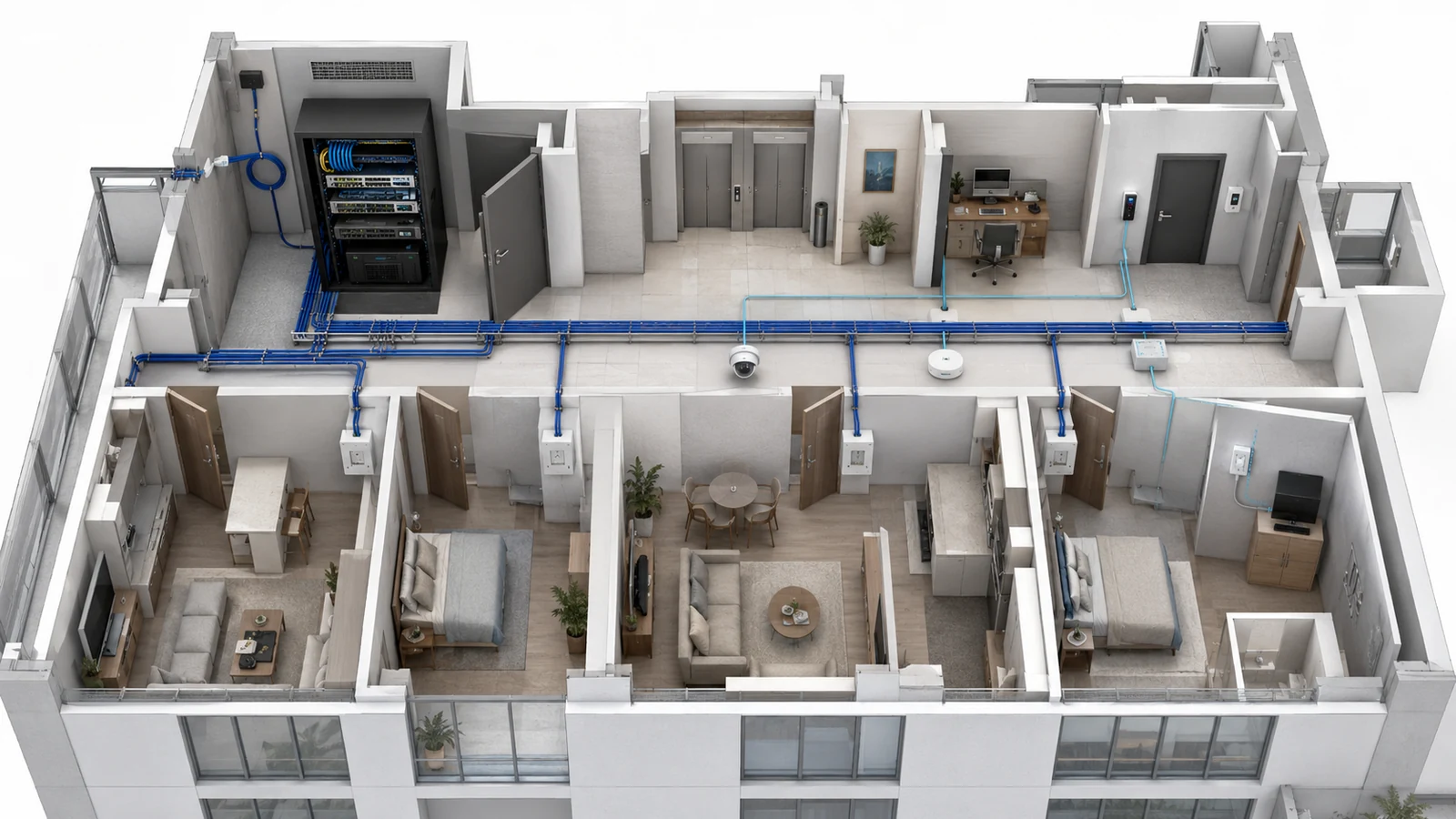
An Intermediate Distribution Frame, or IDF, provides a local distribution point for one floor, several floors, a wing, or another building zone. Some provider architectures use different terminology, but the operational purpose is similar: bring the backbone closer to the endpoints it serves.
An IDF may contain:
- Fiber terminations or optical splitters
- Provider access equipment
- Managed switches and patch panels
- PoE switching for cameras, access points, and controllers
- Local network or building-system interfaces
- UPS equipment
IDF placement should follow the building rather than a rule requiring one room on every floor. The correct arrangement depends on horizontal cable distances, floor shape, unit count, provider architecture, common-area devices, pathway availability, service importance, and room conditions.
Every distribution location should be reviewed for:
- Physical security
- Power and backup expectations
- Heat and ventilation
- Water and plumbing exposure
- Working clearance and maintenance access
- Backbone and horizontal cable organization
- Labeling and ownership
Floor distribution creates smaller service zones, but it does not automatically create redundancy. If every IDF depends on one riser, one core switch, or one power source, those central dependencies remain.
06 The Access Layer: Units, Amenities, and Building Systems
The access layer is where networks reach actual users and devices. In a high-rise, several distinct access environments may coexist.
Residential units may receive:
- Fiber to an optical network terminal
- Ethernet from floor distribution equipment
- Coaxial or another provider-specific medium
- A demarcation point from which the resident manages private in-unit networking
- Building-managed Wi-Fi under a bulk or managed service model
Common areas may include:
- Lobby, lounge, conference, pool, fitness, garage, and rooftop Wi-Fi
- Digital signage and audiovisual systems
- Staff workstations, phones, and printers
- Visitor-management and concierge systems
Operational infrastructure may include:
- Surveillance cameras and recording platforms
- Door, garage, and amenity-access controllers
- Intercom and call-box systems
- HVAC, lighting, water, energy, and other building-management interfaces
- Vendor-managed monitoring devices
These systems may share access switches or telecommunications spaces while remaining logically separated. Public Wi-Fi should not provide a path to building management, cameras, access control, or staff systems.
Specialized systems such as fire alarm, elevator control, emergency communications, and public-safety infrastructure must be coordinated with their responsible professionals. They should not be casually placed on the general building network because an Ethernet connection is available.
07 Topology, Segmentation, and Tenant Isolation
Physical topology explains where cables and equipment are located. Logical topology explains how traffic moves, where routing occurs, and which systems are permitted to communicate.
A building may use:
- A centralized architecture with major routing and policy at the MDF
- Floor or zone aggregation with selected responsibilities in IDFs
- Provider-managed vertical distribution
- A hybrid design combining building-owned and provider-owned systems
Resident isolation depends on the service model. Independently served units may receive separate provider connections and operate private networks behind resident-owned gateways. A building-managed network may require centralized authentication, subscriber management, traffic isolation, and support processes.
Creating one VLAN per unit is not the only isolation method and may not be the correct architecture at scale. Provider platforms, private VLAN behavior, subscriber-management systems, access controls, routing policy, and physical demarcation can all contribute.
Building-operated service groups may include:
- Administration and staff
- Resident or guest amenities
- Surveillance
- Access control
- Building automation
- AV and digital signage
- Vendor systems
- Network management
The detailed guide to network topology in multi-dwelling units explains how physical and logical models should align.
08 Capacity and Resilience Follow Service Dependencies
Capacity planning begins with the services the network supports. Resident internet, amenity Wi-Fi, cameras, access control, staff systems, and building operations may have different traffic patterns and may use separate internet services or backbones.
Review capacity at each relevant layer:
- Carrier or building internet service
- Core routing and switching
- Riser uplinks
- IDF aggregation
- Access-switch ports and PoE budgets
- Wireless capacity in common areas
- Recording, storage, and management platforms
A fast internet circuit cannot correct a congested floor uplink, inadequate switch, poor Wi-Fi placement, or overloaded recorder. Likewise, spare fiber strands do not improve service until suitable active equipment and pathways exist at both ends.
Resilience should be planned by mapping complete service dependencies. For a critical access-control service, those dependencies might include local controllers, switching, backbone links, management servers, internet or cloud connectivity, and power at multiple locations.
Possible resilience measures include:
- Appropriate UPS protection for critical network locations
- Secondary provider service where justified
- Redundant core or distribution equipment
- Diverse backbone pathways
- Local controller behavior during upstream outages
- Configuration backups and replacement procedures
- Documented escalation and recovery responsibilities
Redundancy is not automatically required for every component. It should reflect operational impact, failure probability, available pathways, budget, and the building’s tolerance for downtime.
09 Treat Governance and Documentation as Infrastructure
High-Rise Network Infrastructure Review
- Identify every provider, building, association, resident, and vendor-owned network service.
- Document the physical and administrative demarcation points.
- Map carrier entrances, MDFs, IDFs, risers, pathways, and major endpoint zones.
- Record fiber type, strand use, terminations, patching, and available pathway capacity.
- Confirm horizontal cable distances and the areas served from each IDF.
- Review telecommunications rooms for access, power, UPS, cooling, water, and expansion.
- Separate resident, public, staff, surveillance, access-control, building, vendor, and management services.
- Map capacity at the internet edge, core, riser, floor, access, wireless, and service layers.
- Identify complete dependencies and failure impact for important operational systems.
- Maintain association-controlled accounts, configurations, diagrams, inventories, contracts, and support contacts.
- Define vendor access, change approval, backup, testing, and project-closeout requirements.
- Review infrastructure ownership and documentation during developer, board, management, carrier, or vendor transitions.
High-rise infrastructure must remain understandable through turnover. Developers complete projects, boards change, property-management companies rotate, providers merge, and system vendors are replaced. The building should retain the records and control necessary to maintain its own assets.
Important documentation includes high-level topology diagrams, room and rack layouts, fiber and patching records, equipment inventories, provider demarcations, network segments, administrative ownership, configuration backups, licenses, warranties, and escalation contacts.
The durable parts of a high-rise network are often the least visible: telecommunications rooms, riser pathways, conduits, fiber distribution, unit demarcations, labeling, and ownership records. Active hardware can be replaced more easily when those foundations were designed and documented correctly.
A well-structured high-rise network does not need to place every service under one owner or on one platform. It needs clear boundaries, suitable pathways, serviceable distribution, appropriate security, and enough documentation for every responsible party to understand where its role begins and ends.