
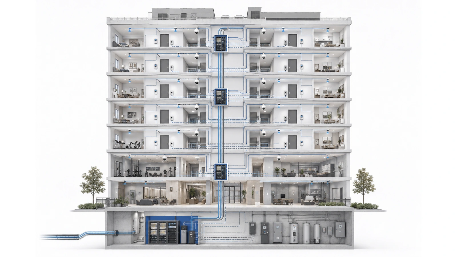
Network topology is the structural map of a multi-dwelling unit, or MDU, network. It describes where equipment and cabling are located, how services move through the building, where security policies are enforced, and which organization controls each part of the system.
That makes topology more than a diagram of switches and cables. It influences tenant isolation, troubleshooting, provider flexibility, backbone capacity, outage impact, equipment-room requirements, and the cost of future changes.
A condominium tower, apartment complex, senior living property, and mixed-use building may all require different topologies—even when they contain similar equipment. The correct architecture must reflect the property’s construction, service model, ownership boundaries, operational capabilities, and actual traffic requirements.
This guide builds on Designing Network Infrastructure for High-Rise Buildings, which explains the broader planning decisions that should be resolved before selecting a topology.
Key Takeaway
An MDU does not have just one topology. It has a physical topology, a logical topology, and an ownership structure. These layers must be designed together, even when different providers and building systems use separate equipment.
01 Physical and Logical Topology Are Different
Two buildings can have nearly identical cable pathways while operating very different networks. Conversely, two networks can apply similar security policies even though their physical distribution systems are not alike.
This is why MDU planning must distinguish between physical and logical topology.
Physical topology
Physical topology describes the locations and pathways that can be seen, accessed, installed, or tested. It may include:
- Carrier entrances and service demarcation points
- Main distribution frame, or MDF, locations
- Intermediate distribution frames, or IDFs
- Telecommunications risers and conduit routes
- Fiber and copper backbone connections
- Horizontal cabling to units and common areas
- Unit demarcation points and resident-facing equipment
Logical topology
Logical topology describes how services and traffic are organized across that physical foundation. It includes:
- Routing and switching boundaries
- Network segments and security zones
- Tenant and client-isolation policies
- Authentication and service-provisioning methods
- Firewall rules and internet access paths
- Management, monitoring, and administrative access
A clean physical installation does not guarantee a secure logical design. Similarly, a sophisticated logical design will remain difficult to support if the cabling, rooms, labels, and pathways are disorganized.
Ownership topology
There is also a third layer: who owns and operates each component. A provider may own the resident-service network while the association owns separate infrastructure for cameras, access control, management systems, and common-area Wi-Fi.
These parallel systems can occupy the same building without forming one unified network. Diagrams should show their relationship without implying that one organization controls everything.
02 The Main MDU Topology Patterns
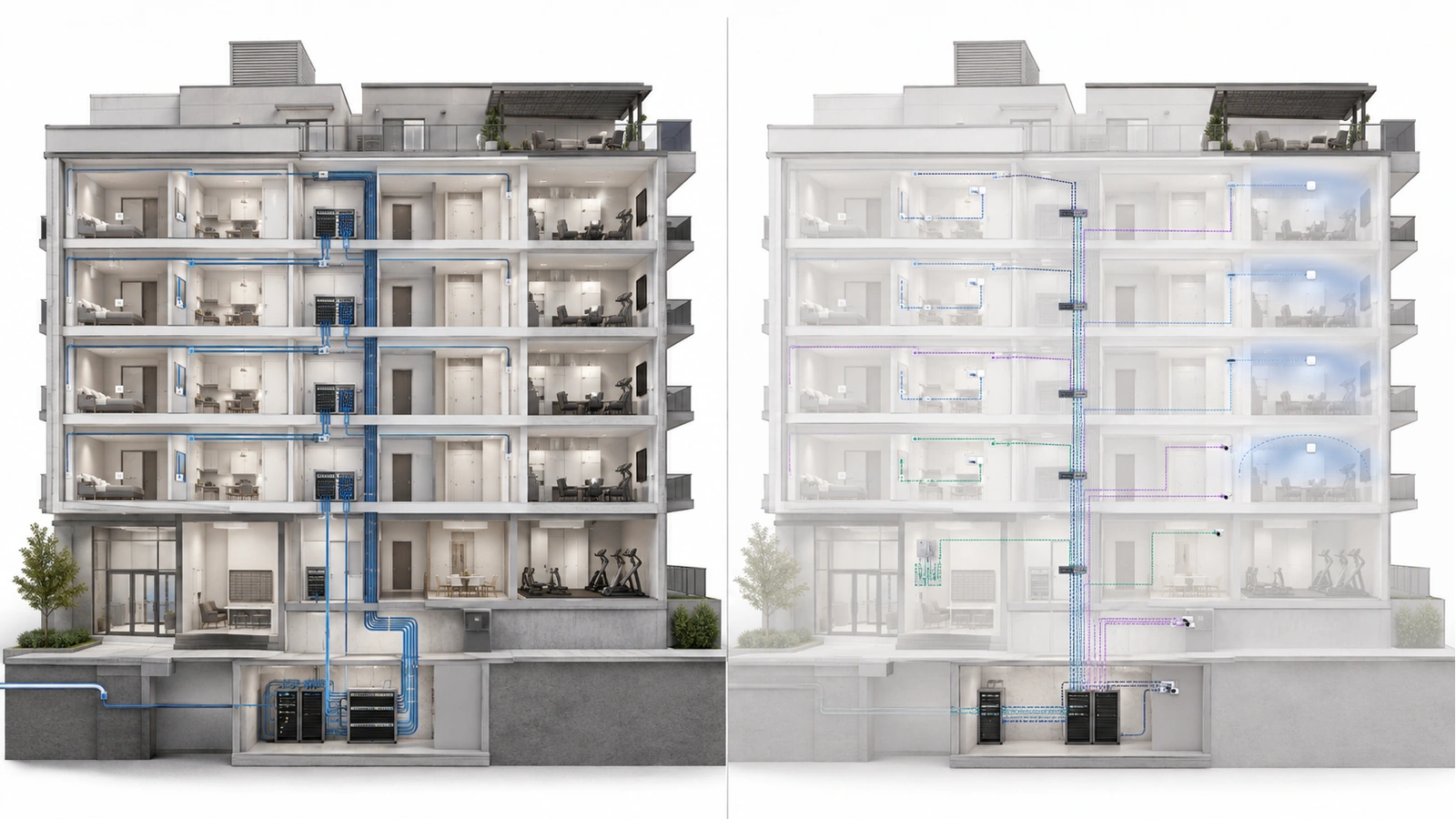
Real buildings often use a combination of architecture patterns rather than one pure model. Four patterns are especially useful for understanding MDU designs:
- Centralized distribution
- Floor or zone distribution
- Fiber-to-the-unit distribution
- Provider-managed distribution
A hybrid property might use provider-owned fiber for resident internet, building-owned floor switches for cameras and access control, and a separate managed wireless system for amenity spaces. The building’s complete topology is therefore a collection of service-specific architectures.
| Topology Pattern | Typical Structure | Important Considerations |
|---|---|---|
| Centralized distribution | Core policy and distribution functions are concentrated in a primary room, with remote switches or passive links extending services. | Simple central administration, but core capacity, room conditions, backbone paths, and failure impact require careful planning. |
| Floor or zone distribution | IDFs aggregate connections from a floor, group of floors, wing, or building zone. | Reduces horizontal distances and localizes equipment, but increases power, cooling, access, and configuration requirements. |
| Fiber to the unit | Fiber extends from a central or distributed optical architecture to a unit demarcation or resident-facing terminal. | Supports long distances and flexible capacity, but optical design, ownership, termination, and endpoint power must be resolved. |
| Provider-managed distribution | A service provider controls some or all of the riser, floor equipment, provisioning platform, and unit delivery. | Reduces building operational responsibility but may limit control, provider replacement, shared-service integration, or upgrade options. |
The chosen pattern should not be based on which diagram looks simplest. It should emerge from pathway conditions, service ownership, cable distances, endpoint requirements, room availability, maintenance capabilities, and acceptable failure domains.
03 Centralized Distribution Does Not Define Every Traffic Path
In a centralized architecture, major routing, firewall, management, or service-delivery functions are concentrated at the building core. Floor switches may primarily extend connectivity from that central environment.
However, centralized management does not automatically mean every packet must travel physically to the MDF and back. Traffic behavior depends on where switching, routing, security enforcement, and service gateways are located.
For example, two devices connected to the same access switch may exchange traffic locally if they belong to the same permitted network segment. If policy requires isolation between them, the switch or an upstream security control may prevent that communication entirely. If routing or inspection is required, the traffic may follow an upstream path to the appropriate gateway.
Centralized designs can offer:
- Consistent policy administration
- Concentrated monitoring and logging
- Fewer locations containing complex routing equipment
- Clear operational control for smaller technical teams
The tradeoffs may include greater dependence on the core, concentrated backbone demand, larger outage impact, and longer paths to certain services. Those risks can be reduced through appropriate capacity, resilient power, redundant components, and carefully designed backbone routes—but only when the complete dependency chain is considered.
04 Floor and Zone Distribution Localizes Infrastructure
A distributed topology places access or aggregation functions closer to the areas they serve. An IDF might serve one floor, several floors, one wing, an amenity level, a parking structure, or another defined zone.
This approach can reduce horizontal copper distances, make endpoint organization clearer, distribute switch capacity, and limit certain equipment failures to a smaller area. It is especially practical where the building contains many wired devices, Power over Ethernet endpoints, or floor-specific systems.
Distribution also introduces additional operational dependencies. Every active IDF may require:
- Reliable electrical service and appropriate backup power
- Ventilation or environmental control
- Secure but practical technician access
- Consistent configuration and firmware management
- Backbone monitoring and documented patching
- Replacement equipment and troubleshooting procedures
Distributed routing may be appropriate when a property has the scale and operational maturity to manage it. It can reduce unnecessary traffic movement and create modular network zones. It also increases the number of locations where routing policy, redundancy, and configuration consistency may matter.
Same-floor traffic should not automatically remain local. Resident isolation, security inspection, service ownership, and application requirements must determine whether devices are allowed to communicate—not their physical proximity.
05 Fiber-to-the-Unit Changes the Distribution Boundary
Fiber-to-the-unit extends optical connectivity deeper into the property, often terminating at an optical network terminal, media device, residential gateway, or unit demarcation point.
This can reduce dependence on active floor switches, avoid copper-distance restrictions, and provide a flexible path for higher-capacity services. It may also create a clearer separation between shared building pathways and resident-facing equipment.
Fiber-to-the-unit is not automatically superior to floor-based switching. Its suitability depends on the optical architecture, provider model, termination strategy, available pathways, unit equipment, power requirements, and responsibility for repairs.
A floor-distribution model using fiber backbone and shorter copper runs may remain entirely appropriate when:
- Floor IDFs already provide secure and suitable equipment space
- Endpoints require Power over Ethernet
- Horizontal cable distances remain within design limits
- The building operates multiple local systems from the same zone
- Maintenance responsibility is clearly assigned
Buildings evaluating these options should review Fiber Distribution Strategies Inside Multi-Dwelling Buildings.
06 Logical Topology Must Enforce Service Boundaries
Logical topology determines which residents, devices, applications, and administrators may communicate. It should reflect both security requirements and organizational responsibility.
A typical property may need distinct environments for:
- Resident internet services
- Resident or guest wireless access
- Property-management operations
- Surveillance cameras and recording platforms
- Access control and intercom systems
- Building automation and environmental systems
- Package, parking, gate, and amenity systems
- Vendor-owned or remotely supported equipment
- Network management and monitoring
These environments may share fiber, switches, racks, or internet circuits without sharing the same trust level. Segmentation can be implemented through VLANs, virtual routing, firewall zones, private VLANs, identity controls, provider platforms, or separate physical infrastructure.
A VLAN per unit is one possible tenant-isolation method, but it is not the universal definition of a secure MDU. At larger scale, a managed platform may use dynamic policy, private client isolation, automated provisioning, subscriber authentication, or other mechanisms.
A VLAN per floor, by itself, usually does not provide meaningful separation between residents on that floor. The design must specify whether client-to-client communication is blocked, where routing occurs, which services are reachable, and how policy is tested.
Topology Does Not Create Isolation by Itself
Placing residents on different floors, switches, or access points does not automatically isolate them. Isolation is a deliberate logical policy that must be enforced consistently across wired, wireless, provider-managed, and building-operated services.
07 Traffic Patterns Determine Capacity Requirements
Backbone sizing should reflect actual service paths rather than a simple count of units. Different systems generate different traffic patterns and operational demands.
Resident internet traffic is commonly north-south traffic moving toward an upstream provider. Surveillance streams may travel continuously from cameras to a local recorder. Access-control devices may communicate with a building server or cloud platform. Wi-Fi management traffic may reach an on-site controller or remote service.
Understanding those flows helps the design team identify:
- Which links aggregate the greatest traffic volumes
- Where oversubscription is acceptable
- Which services require predictable latency or availability
- Whether local traffic should remain within a zone
- Where security inspection and routing should occur
- Which failures could interrupt multiple services simultaneously
Not every connection requires its maximum theoretical capacity at the same moment. At the same time, average usage alone can conceal busy-hour congestion and continuous building-system traffic. Capacity planning should consider peak behavior, service criticality, uplink design, equipment capability, and reasonable expansion paths.
08 Resilience Must Follow the Topology
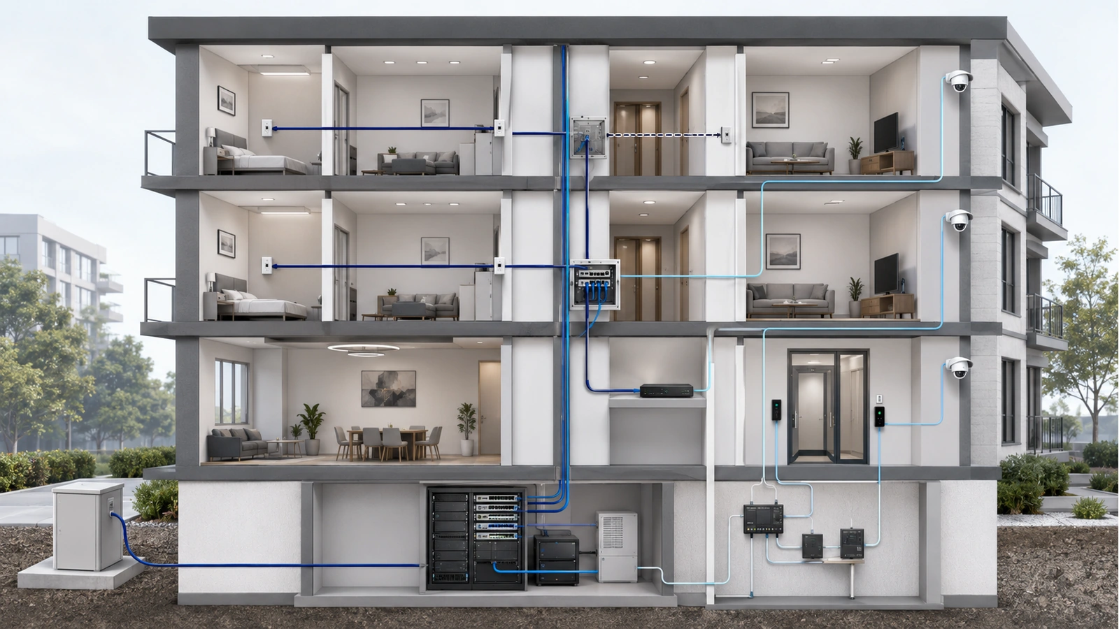
Topology reveals the building’s failure domains—the portions of service affected when a component, room, link, circuit, or provider fails.
A centralized design may place more services behind the same core and MDF dependencies. A distributed design may limit some failures to a floor or zone while creating more powered locations to maintain. Fiber-to-the-unit may remove certain active floor components but still depend on centralized optical equipment and shared pathways.
Effective resilience planning traces the entire service path, including:
- Upstream carrier service
- Building entrance and demarcation
- Core, distribution, and access equipment
- Fiber strands, conduits, and riser routes
- Electrical circuits and backup power
- Cooling and environmental conditions
- Authentication, controller, cloud, or management platforms
- Resident or building endpoint equipment
Two uplinks installed in the same vulnerable pathway may not provide meaningful route diversity. Two switches connected to one electrical circuit remain dependent on that circuit. Multiple internet providers may still share the same external conduit or upstream facility.
Resilience should therefore be documented as an end-to-end service property, not inferred from the number of duplicated devices.
09 Document the Topology Before Deployment
A topology should be reviewed and approved before active equipment is ordered or permanent cabling is installed. The final documentation must be understandable to property representatives, service providers, installers, and future support technicians.
MDU Topology Documentation Checklist
- Carrier entrances and service demarcation points
- MDF, IDF, riser, pathway, and unit-demarcation locations
- Fiber and copper routes with strand, cable, and port assignments
- Ownership of rooms, pathways, cabling, and active equipment
- Core, distribution, access, and unit-facing relationships
- Network segments, routing boundaries, and security zones
- Permitted and prohibited communication between services
- Internet, building-system, and management traffic paths
- Power, backup, cooling, and environmental dependencies
- Expected failure domains and failover behavior
- Monitoring, administrative access, and escalation responsibilities
- Available pathway, fiber, rack, port, and power capacity
Physical and logical diagrams should be maintained separately but cross-referenced. Trying to place every cable, VLAN, IP range, owner, and policy on one drawing usually produces a diagram that is difficult to read and rarely updated.
Topology documentation should also reflect the installed environment rather than only the original design. Moves, additions, provider changes, equipment replacements, and configuration revisions must be recorded through a controlled change process.
A strong MDU topology creates clear relationships between pathways, rooms, services, policies, owners, and failure domains. It does not force every building into one architecture. Instead, it gives the property a structure that can be operated, secured, expanded, and explained.
The next guide examines one of the most consequential physical design decisions in that structure: Fiber Distribution Strategies Inside Multi-Dwelling Buildings.