
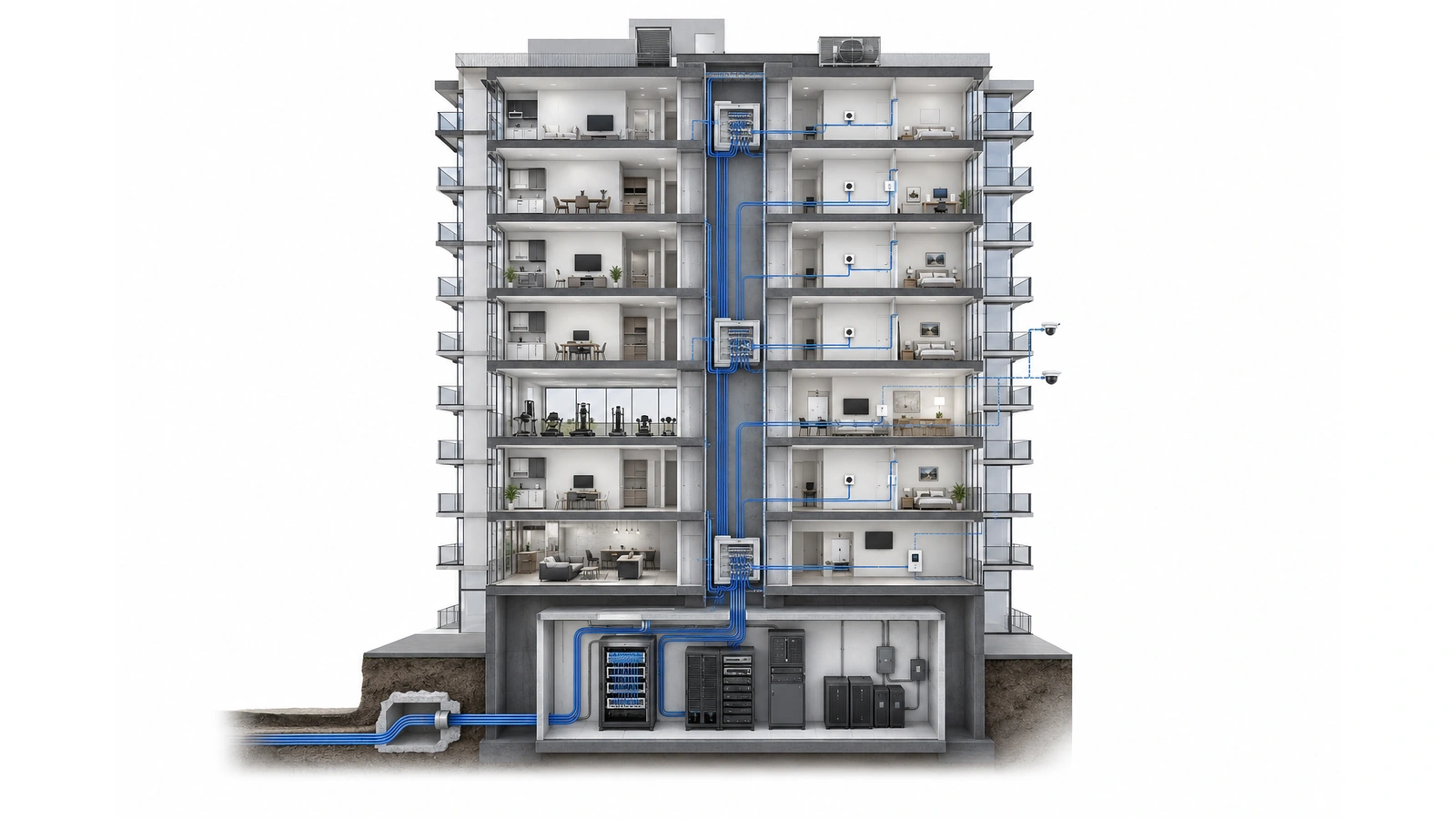
Fiber is the primary vertical distribution medium in many modern multi-dwelling buildings, but simply specifying “fiber backbone” does not create a complete design. The project must determine where fiber begins and ends, how strands are allocated, where active or passive components are placed, who owns them, and how technicians will reach them when service is interrupted.
In one building, fiber may connect the main distribution frame to floor-level network rooms, with copper extending to apartments and building devices. In another, fiber may continue directly into every unit. A third property may contain provider-owned residential fiber alongside a separate building-owned backbone for cameras, access control, management systems, and common-area Wi-Fi.
Each approach can work when it matches the building’s pathways, service model, endpoint requirements, and operational responsibilities. This guide explains the principal choices and how to evaluate them.
For the architectural context behind these decisions, review Understanding Network Topology in Multi-Dwelling Units.
Key Takeaway
The most future-ready fiber design is not necessarily the one containing the greatest amount of fiber. It is the one with usable pathways, appropriate cable and strand capacity, clear ownership, accessible terminations, complete testing, and a practical upgrade path.
01 Separate Backbone, Floor, and Unit Distribution
Fiber planning becomes clearer when the building is divided into three distribution layers.
Building backbone
The backbone connects major telecommunications spaces, commonly beginning near the carrier entrance or MDF and extending through vertical risers to IDFs, equipment rooms, parking structures, amenity buildings, or other zones.
These links carry aggregated services and often support multiple systems. Backbone capacity, pathway protection, termination quality, and restoration options therefore have building-wide consequences.
Floor or zone distribution
At a floor or zone, fiber may terminate in active Ethernet switches, passive optical components, patch enclosures, or provider equipment. Connectivity then continues toward units and local building devices.
The distribution method affects power, cooling, rack space, maintenance access, cable distances, and the number of active components located outside the MDF.
Unit distribution
The final connection may use fiber, copper Ethernet, coaxial cable, or provider-specific media. That selection should reflect the service delivered inside the unit, the location of its demarcation point, endpoint power requirements, and who supports the resident-facing equipment.
These three layers do not have to use one uniform architecture. A building can use fiber between rooms, copper to Power over Ethernet devices, and direct fiber to selected units or specialized endpoints.
02 Compare the Main Distribution Strategies
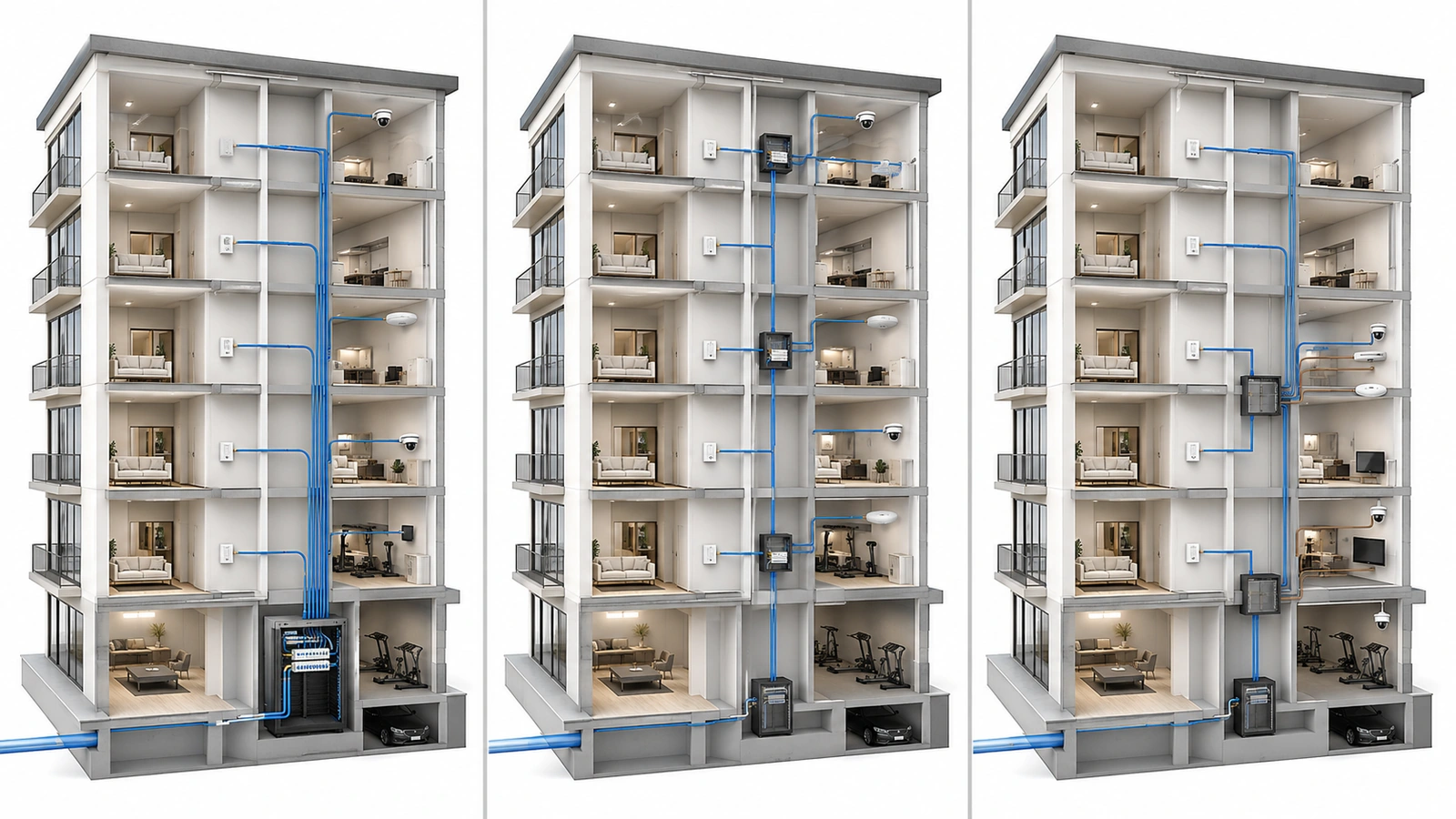
Most MDU fiber designs use one or a combination of the following strategies.
| Distribution Strategy | Typical Architecture | Primary Design Considerations |
|---|---|---|
| Centralized home-run fiber | Individual fiber connections extend from a central distribution location toward units or endpoints. | Requires sufficient riser, enclosure, pathway, termination, and strand-management capacity. |
| Floor-based distribution | Fiber reaches floor or zone IDFs; local connections continue over fiber or copper. | Depends on secure rooms, active-equipment capacity, power, cooling, and accessible maintenance. |
| Fiber to the unit | Optical connectivity extends to a demarcation or termination point inside each residence. | Requires clear ownership, protected unit pathways, suitable termination locations, and endpoint power. |
| Hybrid distribution | Different services or building areas use different fiber and copper distribution methods. | Offers flexibility but requires disciplined documentation and clear service boundaries. |
Centralized home-run fiber can simplify the relationship between a central platform and each destination, but it increases fiber concentration and pathway demand near the core. Floor-based distribution reduces long horizontal runs and can efficiently serve many local endpoints, but it introduces active or passive infrastructure throughout the property.
Fiber-to-the-unit moves the optical boundary closer to residents and can support flexible service delivery. It does not eliminate the need for structured wiring inside the residence, resident-facing electronics, power, Wi-Fi planning, or a clearly defined support boundary.
Hybrid distribution is common because resident internet, cameras, access control, wireless access points, and building automation do not always have identical technical or ownership requirements.
03 Choose Between Active Ethernet and Passive Optical Distribution
The physical route of the fiber is only part of the decision. The design must also determine how services are transported across it.
Active Ethernet
Active Ethernet uses powered switching equipment to aggregate and distribute individual Ethernet connections. In an MDU, switches may be placed in the MDF, floor IDFs, or other secured telecommunications spaces.
This approach can provide familiar Ethernet operations, flexible port configurations, direct monitoring, and straightforward integration with many building systems. It may also support Power over Ethernet on downstream copper connections.
Its requirements include electrical power, heat management, backup-power planning, switch maintenance, software management, and secure access wherever active equipment is installed.
Passive optical networking
A passive optical network uses optical splitters between centralized provider or building equipment and subscriber terminals. The intermediate distribution field can contain passive components that do not require local electrical power.
This can reduce powered equipment in floor rooms and distribute services efficiently across many destinations. However, split ratios, optical loss, connector quality, platform compatibility, provisioning, troubleshooting tools, and ownership must be engineered as a complete system.
Passive distribution is not maintenance-free simply because its intermediate splitters require no power. Connectors can become contaminated, fiber can be damaged, records can become inaccurate, and centralized equipment or subscriber terminals can still fail.
The decision is operational as well as technical
Active Ethernet may fit a building team already prepared to manage distributed switching. A provider-operated passive optical platform may fit a residential-service model with centralized provisioning. Some properties use both: one for resident services and another for building operations.
The selection should be made by evaluating the entire service lifecycle, not by comparing headline bandwidth alone.
04 Decide How Far Fiber Should Extend
Fiber-to-the-unit is often presented as the most advanced option, but extending fiber farther is beneficial only when the termination and service model are well planned.
A direct unit connection can offer:
- Long-distance capability without copper Ethernet limitations
- Substantial capacity and electronics-upgrade flexibility
- Reduced dependence on powered floor-distribution equipment
- A defined optical connection for individual service delivery
It also creates practical questions:
- Where will the fiber terminate inside the unit?
- Who may access, repair, or replace that termination?
- How is the cable protected during renovations?
- Where will the residential gateway or optical terminal receive power?
- How will connectivity be distributed throughout the residence?
- Who supports the resident when the optical link is healthy but the in-unit network is not?
A fiber backbone with floor-based copper remains legitimate when cable distances are suitable, IDFs provide dependable operating conditions, and local endpoints benefit from Ethernet or Power over Ethernet. The copper category, termination quality, pathway environment, and switch capability must still match the intended application.
The correct question is not simply, “Can we put fiber in every unit?” It is, “Where should the service demarcation and active-electronics boundaries be placed so the system remains supportable?”
Design Principle: Fiber Does Not Replace the In-Unit Network
Fiber can deliver excellent capacity to a residence, but residents still need an appropriate gateway, wired distribution, and Wi-Fi coverage. A poorly placed unit termination can undermine an otherwise strong building design.
05 Design Pathways as Long-Term Infrastructure
The most difficult fiber limitations are often caused by pathways rather than the cable itself. Fiber must be routed through risers, sleeves, conduits, trays, corridors, equipment rooms, and unit entrances while remaining protected and accessible.
A pathway survey should evaluate:
- Available riser and horizontal pathway capacity
- Pull distances and access points
- Cable support and pathway organization
- Bend-radius and pulling-tension requirements
- Fire-rated penetrations and approved firestopping
- Exposure to water, heat, chemicals, construction, or physical damage
- Separation and coordination with electrical and mechanical systems
- Access restrictions in occupied or secured areas
- Space for future cable installation and safe removal
Fiber should not be placed in an inaccessible route simply because that route is available during construction. Future technicians must be able to locate, inspect, test, repair, and replace the infrastructure without unnecessary disruption.
New construction should reserve suitable telecommunications pathways before other trades consume the available space. Existing buildings may need staged pathway improvements, new conduit, or alternative routes before the preferred fiber architecture becomes practical.
06 Plan Cable Types, Strands, and Terminations Together
Fiber specifications should be selected according to the intended application, transmission distance, electronics, connector strategy, pathway rating, and ownership model. A generic requirement such as “install fiber” leaves too many critical decisions unresolved.
Single-mode fiber is widely used for building backbones and provider services because it supports long distances and broad upgrade flexibility. Multimode fiber may remain suitable for certain shorter in-building applications, particularly when it aligns with existing equipment and infrastructure.
The design should document:
- Fiber type and cable construction
- Required environmental and pathway rating
- Strand count and allocation
- Connector and termination method
- Splice, splitter, enclosure, and patch-panel locations
- Polarity and color conventions
- Service owner and permitted users of each strand group
- Testing and acceptance criteria
Installing reasonable spare strand capacity during initial construction can provide valuable flexibility. However, strand count should be based on service assignments, topology, expected expansion, restoration needs, and pathway constraints—not an arbitrary multiplier.
Spare conduit or innerduct can be more valuable than a large cable installed without a clear allocation strategy. A future provider may require a separate pathway, different ownership boundary, or cable type rather than unused strands inside another organization’s cable.
07 Distinguish Spare Capacity from Redundancy
Spare strands help restore or expand a service when usable fibers remain available in the same cable. They do not protect against every failure.
If construction damages the entire cable, water affects the same enclosure, fire blocks the riser, or technicians lose access to the shared pathway, all strands in that cable may become unavailable simultaneously.
Meaningful fiber resilience may require:
- Alternative building entrances
- Physically separated riser or conduit routes
- Diverse links to critical distribution areas
- Protected and separately located termination points
- Compatible failover equipment and configurations
- Monitoring that identifies partial link degradation
- Documented restoration procedures and available replacement materials
Not every service requires fully diverse infrastructure. The resilience level should reflect the consequences of an outage and the realistic operating budget.
Resident convenience services, property operations, access control, and regulated communications may have different availability requirements. Infrastructure associated with life-safety or code-regulated systems must be designed and approved by the appropriately qualified professionals.
08 Keep Services and Ownership Boundaries Clear
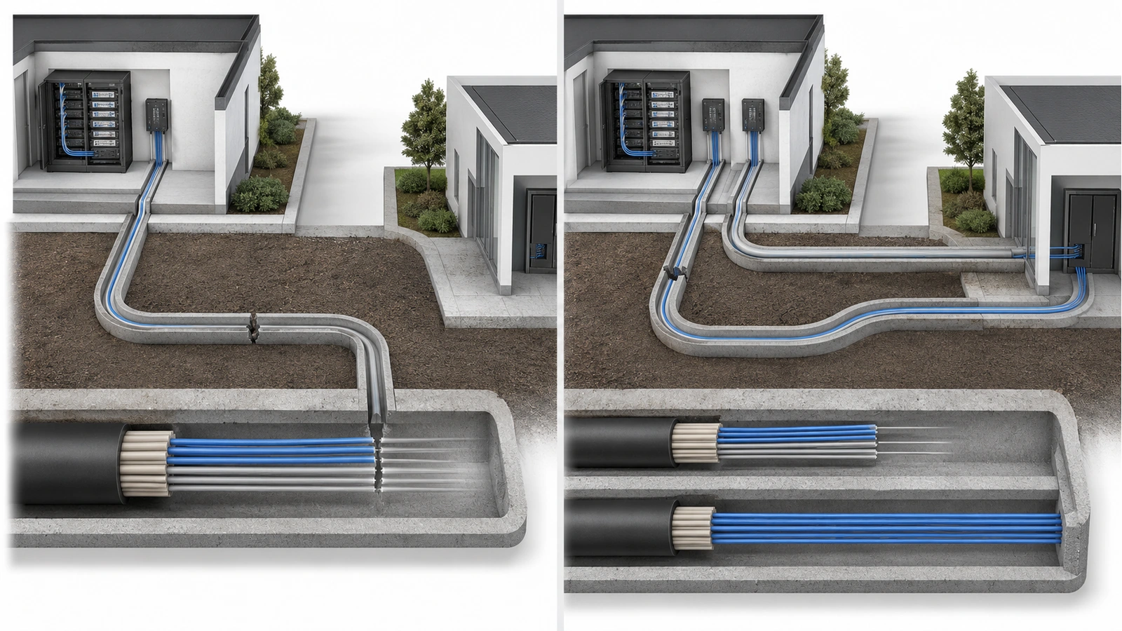
A common fiber backbone can carry multiple logically separated services, but shared transport does not erase security or ownership boundaries.
Resident services, common-area Wi-Fi, cameras, access control, management operations, and vendor systems may require separate fibers, wavelengths, virtual networks, security zones, or physical platforms depending on the design.
The building should understand:
- Which organization owns each cable and termination enclosure
- Which strands are assigned to each provider or service
- Who may patch, test, or modify those strands
- Whether another provider can use the same pathways
- Who responds to backbone, floor, and unit-side failures
- What happens to the infrastructure if a vendor is replaced
Provider-owned fiber may reduce the association’s maintenance burden while limiting control over upgrades or replacement. Building-owned passive infrastructure may increase flexibility while placing documentation, testing, and restoration responsibilities on the property.
These choices connect directly to the building’s broader service model. Continue later with Shared vs. Private Networks in MDUs for a deeper examination of ownership and resident-service boundaries.
09 Test and Document Before Acceptance
A fiber installation should not be accepted solely because devices establish a link. Every permanent connection should be identified, tested according to the project requirements, and matched to the as-built documentation.
Fiber Infrastructure Acceptance Checklist
- Confirm cable type, strand count, pathway rating, and installed route
- Inspect enclosures, supports, bend management, and cable protection
- Verify that penetrations are appropriately sealed and documented
- Label both ends, intermediate enclosures, panels, ports, and assigned strands
- Clean and inspect connector end faces using appropriate procedures
- Complete the specified insertion-loss and link testing
- Perform additional characterization where required by the design
- Record equipment-room, splice, splitter, and termination locations
- Document provider, building, vendor, and resident demarcation points
- Reserve and identify spare strands without leaving ambiguous connections
- Deliver test results, route drawings, strand schedules, and warranty records
- Define who authorizes future patching, testing, and infrastructure changes
Fiber connectors are especially sensitive to contamination. Proper inspection and cleaning practices should be part of installation and maintenance—not reserved for troubleshooting after performance becomes unstable.
Documentation should be updated whenever strands are reassigned, providers change, splitters or enclosures are added, equipment rooms are modified, or restoration work is completed. An accurate strand schedule can reduce hours of disruptive investigation during an outage.
A strong fiber strategy gives the building options. It provides protected pathways, usable capacity, accessible terminations, verified performance, and clearly assigned responsibility. Whether fiber ends in an IDF or continues into every residence, the infrastructure should support the building’s actual services without creating unnecessary operational complexity.
For the larger planning framework surrounding this work, return to Designing Network Infrastructure for High-Rise Buildings.