
Introduction
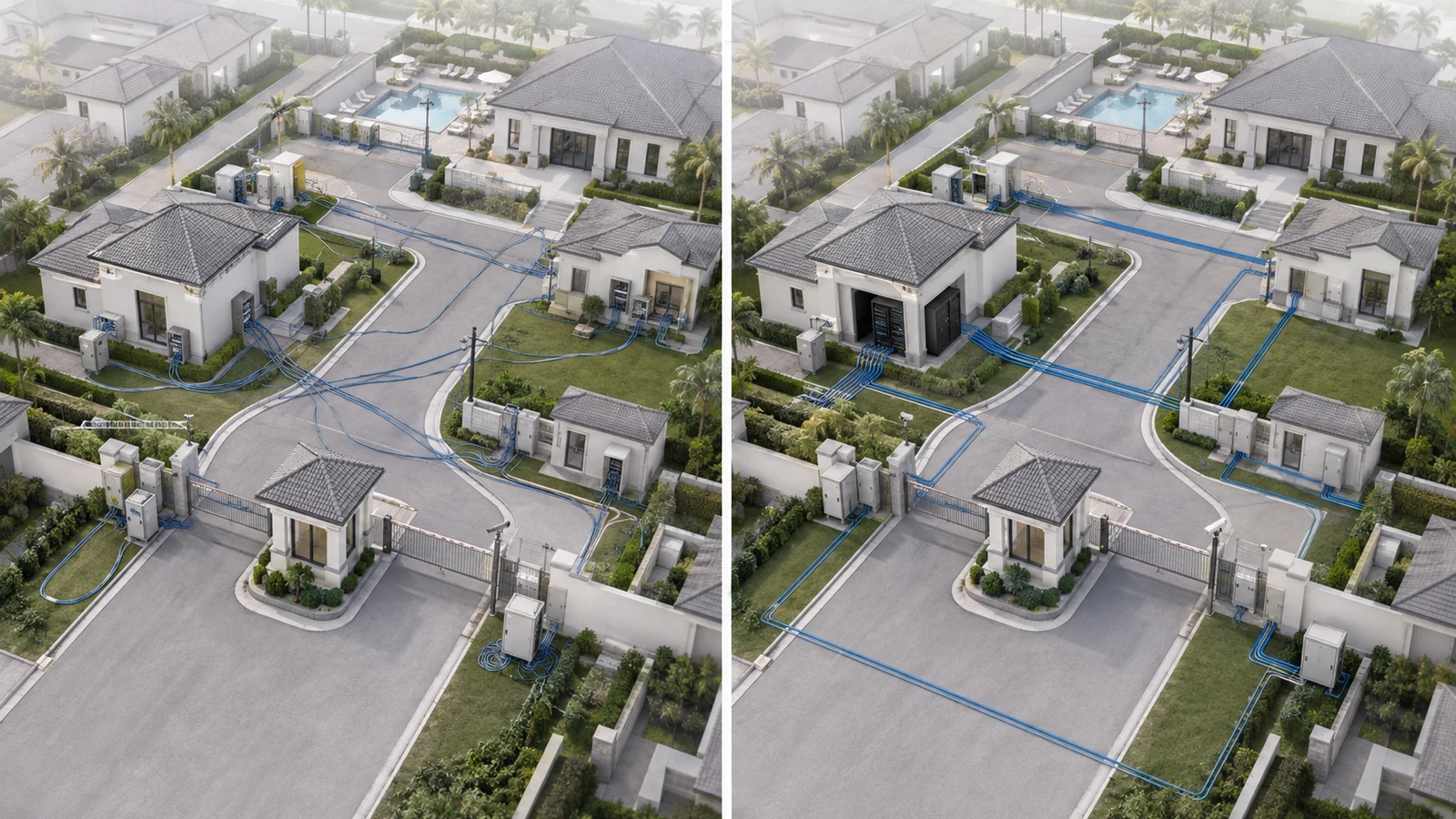
Most chronic HOA network problems are not caused by one defective switch or an underperforming access point. They begin much earlier—with unclear ownership, improvised connections, poorly selected pathways, weak security boundaries, undersized equipment spaces, and projects purchased one system at a time without an overall architecture.
The result may appear manageable while the network is small. Over time, however, cameras, access control, guest Wi-Fi, office systems, cloud platforms, audiovisual equipment, and building controls accumulate. Each new project adds another switch, account, vendor, enclosure, or dependency until no one can clearly explain how the property’s technology fits together.
The problem is not that every community needs enterprise complexity. It is that shared infrastructure must be designed and governed as a property system rather than as a collection of unrelated devices.
01 Mistake 1: Treating the Community Like a Large Home Network
A home network normally serves one household under one ownership model. Community infrastructure may serve property management, staff, gatehouses, clubhouses, cameras, access control, fitness facilities, restaurants, outdoor amenities, building systems, vendors, residents, and visitors.
Connecting all of those systems through one flat collection of switches and Wi-Fi networks may appear simple, but it obscures important differences:
- Who owns each system
- Who is authorized to administer it
- Which services may communicate
- Which vendor supports each component
- What happens when a connection or device fails
- Which services are operationally critical
The correction is not to make the network unnecessarily complicated. It is to establish a layered structure with a controlled internet edge, dependable backbone, organized building distribution, disciplined endpoint connections, and clearly defined service boundaries.
The foundational guide to how Community and HOA networks are structured explains how those layers work together.
02 Mistake 2: Building the Backbone Around Convenience
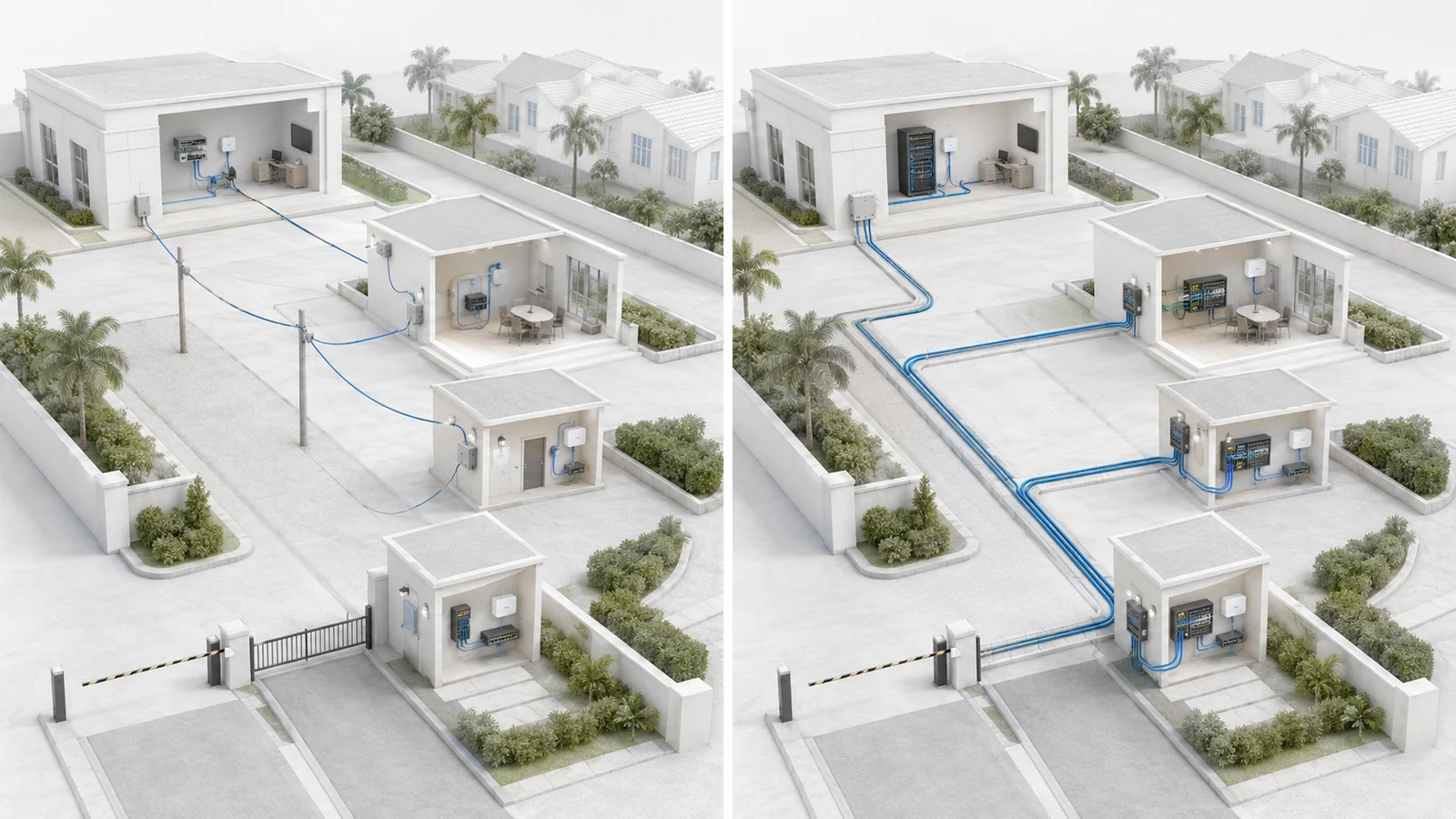
Inter-building connectivity is frequently designed around the easiest available route or the least expensive immediate proposal. A cable is extended from one structure to another because the connection works today, while pathway capacity, electrical conditions, distance, environmental exposure, and future expansion receive limited attention.
Backbone infrastructure should be evaluated differently from ordinary endpoint cabling. It may carry traffic for entire buildings, security systems, amenities, or remote network locations. A failure can therefore affect far more than one device.
Fiber is often the preferred medium between buildings because it supports long pathways, provides electrical isolation between structures, and offers substantial capacity. However, specifying “fiber” alone is not a complete design. The project must also address:
- The physical pathway and available conduit
- Fiber type and strand count
- Termination locations and enclosure protection
- Compatible network interfaces and optics
- Testing and documentation
- Spare capacity and future building connections
- Repair access if the pathway is damaged
Copper may remain appropriate within buildings and for carefully evaluated applications. Between separate structures, it introduces distance, surge, grounding, and environmental considerations that require qualified design.
The detailed guide to fiber versus copper between HOA buildings provides a more complete decision framework.
03 Mistakes 3 and 4: Flat Networks and Blurred Service Boundaries
A flat network places many unrelated systems within the same logical environment. Administrative computers, public Wi-Fi, cameras, access control, building controls, and vendor equipment may be able to discover or reach one another simply because no deliberate boundaries were created.
This causes more than a theoretical security concern. It also complicates troubleshooting, vendor responsibility, network changes, and incident containment.
Common service groups may include:
- Property management and administration
- Staff devices
- Resident and visitor Wi-Fi
- Surveillance and recording systems
- Access control and gate equipment
- Building automation and operational technology
- Restaurant or payment-related systems
- Audiovisual and event systems
- Vendor-managed devices
- Network-management interfaces
The correction is not necessarily to create a separate VLAN for every device type. The design should group systems according to ownership, risk, operational dependencies, and support requirements. Communication between those groups should then be limited to what the property actually needs.
For example, public Wi-Fi generally needs internet access without a path to administrative computers, cameras, or building controllers. Surveillance devices may need to communicate with an approved recorder and management workstation without being open to every staff or guest device.
Logical segmentation must also be matched by operational controls. Shared passwords, undocumented remote access, and vendor-owned administrator accounts can undermine a technically sound VLAN and firewall design.
04 Mistake 5: Treating Equipment Rooms as Leftover Space
Primary and secondary network locations are often placed wherever unused wall or closet space happens to exist. They may share rooms with cleaning supplies, plumbing, irrigation equipment, electrical panels, stored furniture, or general maintenance materials.
As more systems are added, the property encounters:
- Congested racks and cabinets
- Inaccessible patch panels
- Insufficient electrical capacity
- Inadequate UPS capacity
- Poor ventilation and excessive heat
- Unlabeled cables and unmanaged service loops
- Water, dust, pests, or accidental physical exposure
- No room for new circuits, switches, or fiber terminations
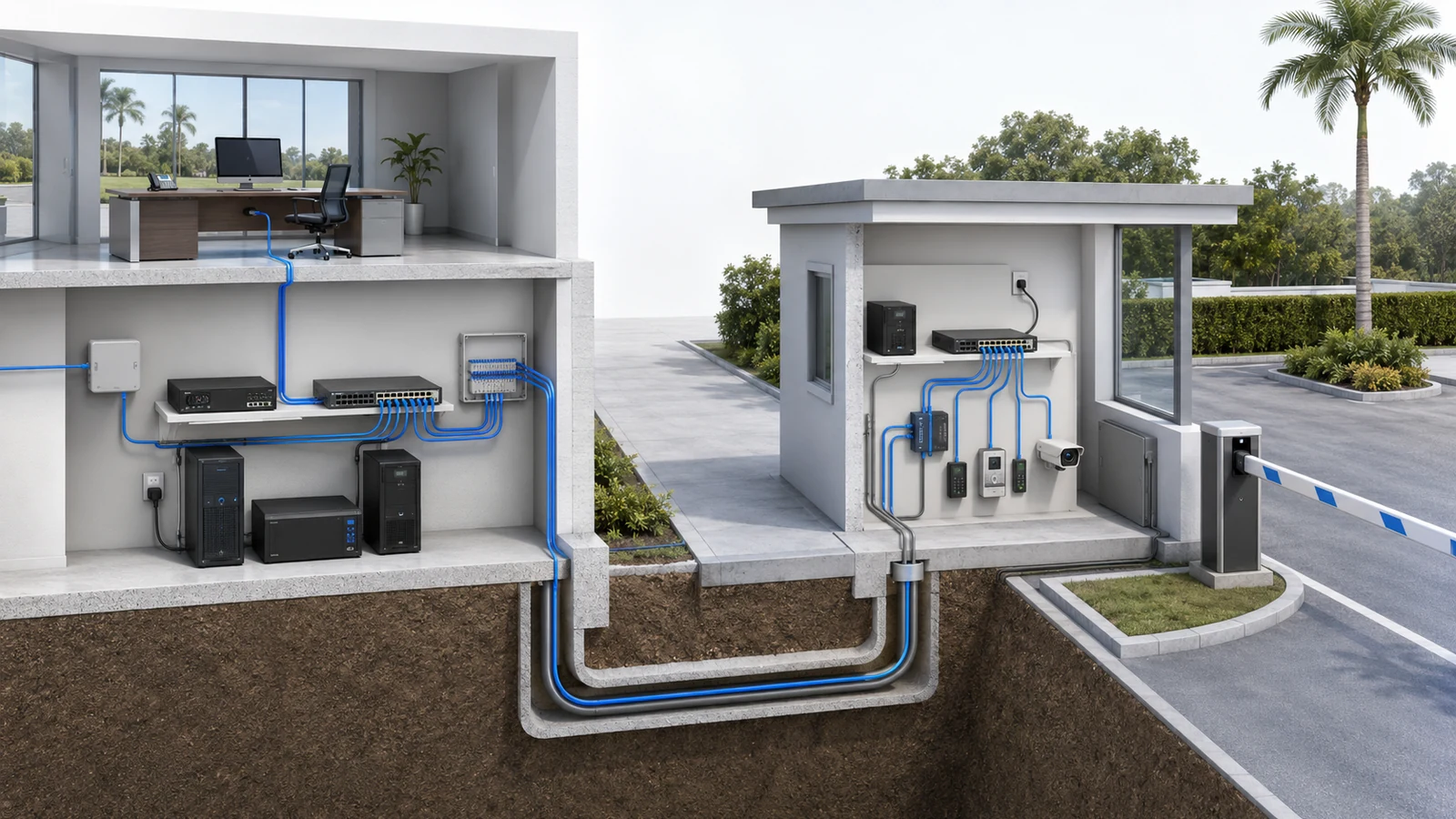
The MDF or primary equipment room does not need to resemble a commercial data center. It does need to provide a secure, serviceable, and environmentally appropriate home for the systems the community depends on.
Remote buildings may use smaller IDF rooms, wall-mounted racks, or secured cabinets. The format can vary, but each location should have documented power, cooling, physical access, patching, uplinks, and equipment ownership.
Physical disorder eventually becomes operational disorder. A network cannot remain easy to support when technicians cannot trace a cable, reach the back of a device, identify a circuit, or determine which vendor installed an enclosure.
05 Mistake 6: Confusing Backup Equipment With Resilience
Installing a second internet circuit, an additional switch, or a larger UPS does not automatically make a community network resilient. Redundancy only provides value when the complete service path can use it and the transition has been designed and tested.
Consider a gatehouse that depends on several connected elements:
- Internet or private connectivity
- The main gateway and core switching
- An inter-building backbone link
- A local access switch
- The gate controller and entry equipment
- Cloud or on-site management services
- Power at several locations
A backup ISP at the clubhouse may not help if the gatehouse switch loses power or the only fiber pathway is damaged. Similarly, keeping cameras powered does not preserve recording if the recorder, uplink, or supporting storage is unavailable.
Resilience planning should begin with operational impact:
- Identify the services that matter most during an outage.
- Map the complete dependency path for each service.
- Identify the single points of failure along that path.
- Decide which failures justify mitigation.
- Document the expected behavior and available runtime.
- Test the result under controlled conditions.
Not every service requires automatic failover or duplicated equipment. The appropriate level of protection depends on safety, access, operations, cost, and the community’s tolerance for downtime.
06 Mistake 7: Designing Exactly to Today’s Requirements
A proposal may technically satisfy the current device list while leaving no practical margin for the next camera, access point, amenity, office renovation, or building-control integration.
Common capacity constraints include:
- No available switch ports
- Insufficient PoE power for additional devices
- Backbone links selected only for current traffic
- Conduit without spare pathway capacity
- Racks and cabinets already filled
- UPS systems operating near their practical load
- Limited fiber strands or unavailable termination space
- Licensing or management platforms at their supported limit
Planning for growth does not mean purchasing twice as much equipment or predicting every future project. It means avoiding infrastructure choices that make reasonable expansion unnecessarily disruptive.
The most durable investments are often pathways, equipment locations, structured cabling, labeling, documentation, and modular switching. Those elements allow active hardware to change without forcing the community to reconstruct the physical network every time requirements increase.
Growth planning should be tied to the property’s actual capital plan. Planned clubhouse renovations, new gate systems, camera expansions, outdoor Wi-Fi, building additions, and amenity upgrades provide more useful guidance than a generic device multiplier.
07 Mistakes 8 and 9: Weak Documentation and Vendor Dependence
Many communities discover the true condition of their network only when the current provider leaves, a major failure occurs, or a replacement project begins. Credentials are missing, diagrams are outdated, configurations exist only on a vendor’s computer, and no one knows which accounts are controlled by the association.
Using one primary technology partner is not inherently a problem. Standardization and a strong provider relationship can make support more consistent. The risk begins when the association cannot operate, recover, audit, or transition its own infrastructure without that provider’s cooperation.
The community should retain controlled access to:
- Administrative accounts and account-recovery methods
- Current network and system diagrams
- Gateway, switch, wireless, and controller configurations
- Configuration backups and documented restoration procedures
- ISP accounts and circuit information
- Licenses, subscriptions, cloud portals, and renewal dates
- Device inventories, serial numbers, and warranty records
- Patch-panel, switch-port, and fiber-termination records
- Vendor support responsibilities and escalation contacts
- Records of material changes
This information should be stored securely and made available according to defined roles. It should not be scattered through personal email accounts, shared informally between board members, or left solely with a contractor.
Vendor transitions should include the return of credentials, backups, documentation, licenses, and association-owned equipment. A network should remain supportable even when the people responsible for it change.
08 Mistake 10: Evaluating Hardware Before Architecture
Boards naturally focus on visible proposal details: brands, model numbers, quantities, warranty periods, and total price. Those details matter, but they do not reveal whether the design solves the community’s underlying problem.
Two proposals with similar equipment can represent very different architectures. One may include documented pathways, appropriate security boundaries, tested failover behavior, configuration ownership, and capacity for planned growth. The other may simply replace old devices in the same flawed structure.
| Common Mistake | Likely Operational Consequence | Architectural Correction |
|---|---|---|
| Oversized home-network approach | Unclear roles, fragile expansion, and difficult troubleshooting | Define edge, backbone, distribution, access, security, and governance layers |
| Convenience-based backbone | Distance, environmental, repair, or capacity limitations | Design pathways and inter-building media as long-term property infrastructure |
| Flat network | Excessive trust between unrelated systems | Group services by purpose and enforce necessary communication boundaries |
| Blurred user access | Public, resident, staff, and administrative traffic become difficult to control | Separate roles and define appropriate access for each user group |
| Improvised equipment spaces | Heat, power, physical-access, and maintenance problems | Provide secure, serviceable rooms or cabinets with suitable environmental conditions |
| Untested redundancy | Backup equipment exists but critical services still fail | Map complete dependencies and test the expected outage behavior |
| No expansion margin | Routine additions require early replacement or reconstruction | Align capacity with known projects and preserve modular growth paths |
| Missing documentation | Slow recovery, risky changes, and expensive discovery work | Maintain diagrams, inventories, configurations, accounts, and change records |
| Vendor dependence | The association cannot recover or transition its own systems | Retain administrative control, backups, records, and contractual handoff requirements |
| Hardware-first purchasing | New devices reproduce the same underlying limitations | Approve the architecture, responsibilities, and outcomes before selecting products |
A strong proposal should explain the current limitation, the intended architecture, the implementation phases, the operational impact, the ownership model, and the acceptance criteria. Equipment should support those decisions rather than substitute for them.
When approval is required, the guide to presenting a network upgrade plan to an HOA board explains how to translate technical requirements into a clear decision package.
09 Correct the Structure in a Controlled Sequence
HOA Infrastructure Correction Checklist
- Identify every association-owned technology service and its operational purpose.
- Document what is owned by residents, providers, contractors, and the association.
- Create a high-level map of buildings, equipment locations, backbone links, and major systems.
- Record the current internet edge, gateways, switches, access points, controllers, and recorders.
- Identify flat networks, uncontrolled access, shared credentials, and undocumented vendor connections.
- Review inter-building pathways, media, terminations, environmental exposure, and repair access.
- Assess MDF and IDF power, UPS capacity, cooling, physical security, and available space.
- Map dependencies and failure impact for critical operational services.
- Compare existing capacity with approved or likely property projects.
- Secure association-controlled credentials, backups, diagrams, inventories, and service records.
- Prioritize corrections by risk, operational impact, dependency, and implementation practicality.
- Define acceptance testing and documentation requirements before authorizing major work.
Not every inherited problem must be corrected at once. A community can begin by documenting the current environment, resolving account ownership, separating the highest-risk services, protecting critical equipment locations, and creating a phased backbone or switching plan.
The durable lesson is that community technology should be managed as infrastructure. Hardware eventually becomes obsolete, vendors change, and property needs evolve. A clear architecture allows those changes to happen without repeatedly rebuilding the network from the beginning.
When architecture, ownership, documentation, and operational priorities lead the project, the network becomes easier to secure, support, explain, and improve. When device purchases lead, the community often receives newer equipment without a more reliable system.