
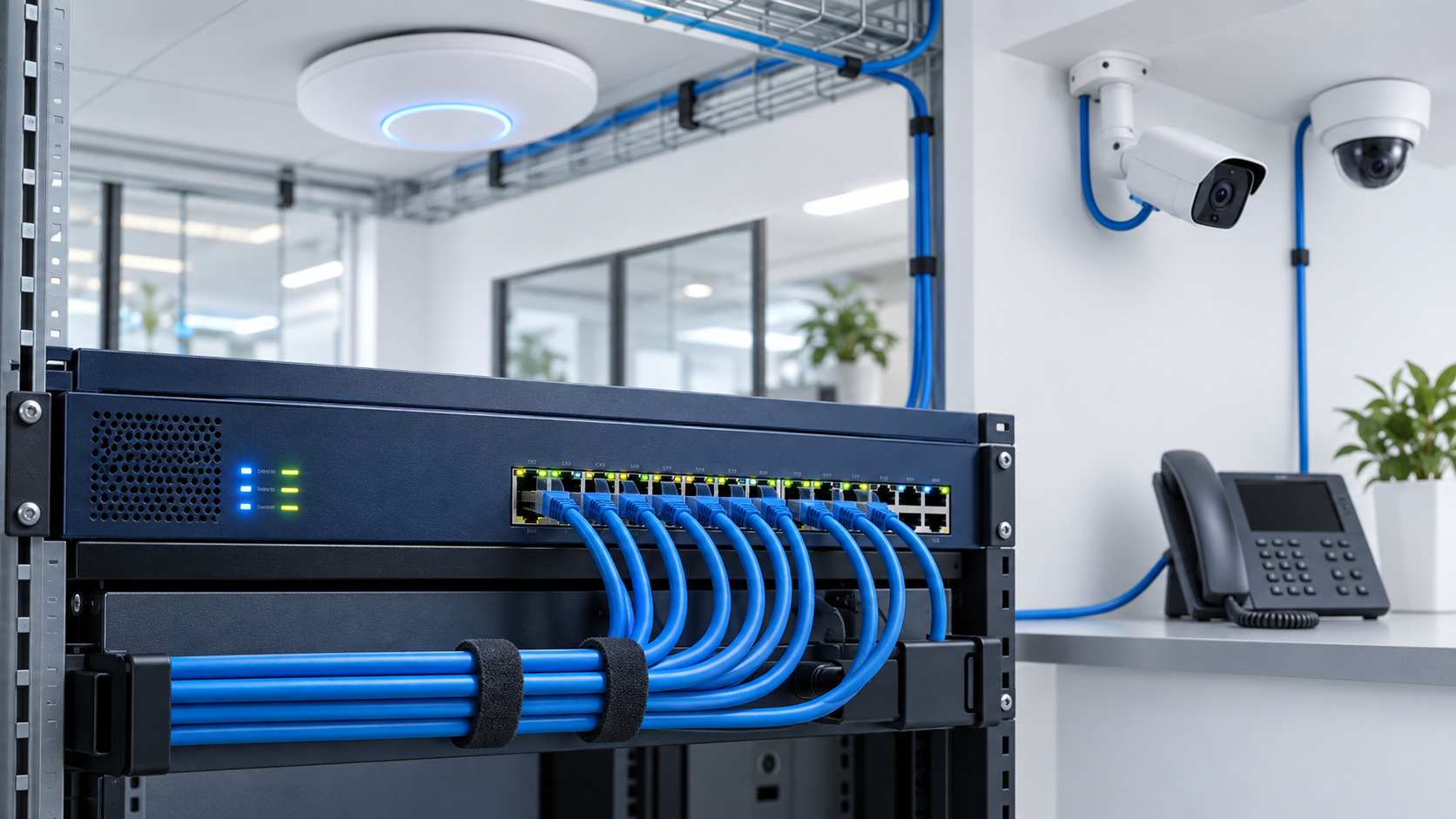
Calculating a PoE switch power budget requires more than adding the wattage printed beside a few devices. A reliable plan must account for every powered device, its maximum demand, the switch’s total PoE capacity, individual port limits, available port count, and enough reserve for startup conditions and future expansion.
A switch may have enough Ethernet ports while still lacking enough power to operate all connected access points, cameras, phones, intercoms, and controllers at their required levels. The opposite can also occur: the switch may provide enough total wattage but lack the correct PoE standard or per-port output for one demanding device.
The calculation itself is straightforward once the correct values are collected. The challenge is knowing which specifications to use and avoiding assumptions that make the result look safer than it really is.
This guide focuses specifically on calculating and evaluating switch capacity. For the underlying standards, device roles, cabling considerations, and differences between PoE, PoE+, and PoE++, see PoE Explained: Powering Access Points, Cameras, and More.
Key Takeaway
Calculate the maximum planned device load, verify that every device fits within the switch’s per-port capability, confirm that enough PoE-capable ports are available, and preserve reasonable reserve capacity. Do not select a switch from port count or ordinary observed consumption alone.
01 Identify the Correct Switch Specifications
Begin with the specifications of the actual switch or power-supply configuration being considered. Do not use the switch’s total electrical input rating as its PoE budget.
The calculation requires four switch values:
- Total PoE budget: The combined power the switch can provide to connected powered devices.
- PoE-capable port count: The number of ports that can deliver power, which may be lower than the switch’s total Ethernet port count.
- Per-port capability: The maximum power or PoE standard supported by an individual port.
- Power-supply conditions: Any limitations or changes caused by the installed power supply, redundant-power configuration, model variant, or operating mode.
A 24-port switch does not necessarily provide PoE on all 24 ports. Likewise, a switch advertising high-power PoE on selected ports may not have enough total budget to operate every port at that level simultaneously.
Use the manufacturer’s documentation for the exact model and power-supply configuration. Product-family summaries and reseller descriptions may combine several variants with different power capabilities.
Do Not Confuse AC Input With PoE Output
The switch’s total AC power rating includes its own operation and conversion losses. Use the documented PoE budget available to powered devices—not the maximum electrical draw listed for the complete switch.
02 Build an Inventory of Every Powered Device
Create a device list before performing the calculation. Include equipment that will be installed immediately as well as approved additions that the switch is expected to support.
Typical powered devices include:
- Wireless access points
- Fixed and pan-tilt-zoom security cameras
- VoIP phones
- Video doorbells and intercoms
- Access-control devices
- Touch panels and room controllers
- Network bridges and compact switches
- Digital displays and specialized building devices
For each device type, record:
- Device name or model
- Quantity
- Expected operating consumption
- Maximum power requirement
- Required PoE standard or class
- Whether optional features increase consumption
Similar-looking devices can have very different requirements. A basic fixed camera may consume relatively little power, while a camera with infrared illumination, heating, motorized movement, audio, or other enabled features may require substantially more.
Access points can also increase consumption when additional radios, USB devices, high client activity, or advanced features are active. Use documentation for the actual model rather than a generic estimate for the device category whenever possible.
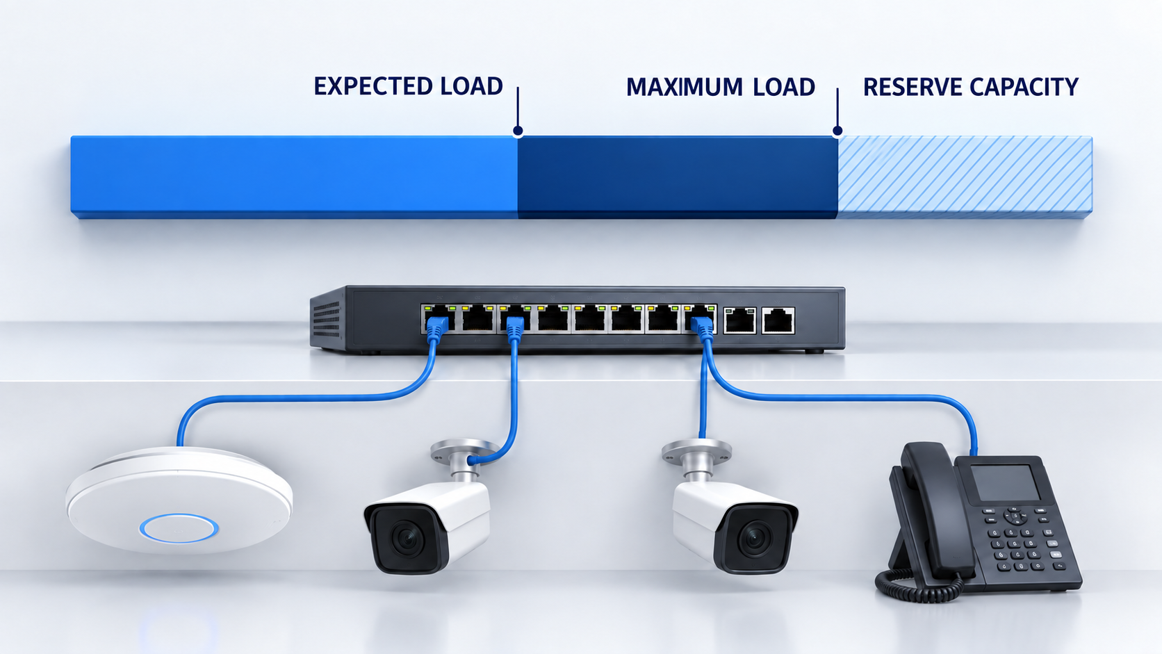
03 Separate Expected Load From Maximum Load
Expected consumption and maximum consumption answer different planning questions.
Expected load estimates what the devices may consume during ordinary operation. It is useful for understanding typical demand, monitoring the deployed system, and planning upstream power or battery-backup requirements.
Maximum load represents the documented or reasonably planned upper demand of the connected devices. It is the safer value for determining whether the switch can support the design.
| Load Type | What It Represents | Primary Planning Use |
|---|---|---|
| Expected load | Likely consumption during ordinary operation | Operational monitoring, typical power use, and preliminary UPS planning |
| Maximum load | Highest documented or planned demand with relevant features active | PoE switch sizing, per-port verification, and capacity protection |
Do not size the switch exclusively from a management dashboard showing current consumption. That snapshot may not include startup behavior, infrared illumination at night, camera heaters, motor movement, radio activity, attached USB devices, or features that will be enabled later.
Observed consumption is valuable after deployment, but it does not replace documented maximum requirements during initial planning.
04 Calculate the Combined Device Load
Calculate each device group separately by multiplying the quantity by the wattage required per device.
Expected load for a device group:
Quantity × Expected watts per device
Maximum load for a device group:
Quantity × Maximum watts per device
Add the results for every device group:
Total expected load = Sum of all expected device-group loads
Total maximum load = Sum of all maximum device-group loads
For example, consider a small installation containing:
- Two wireless access points using 11 watts expected and 18 watts maximum each
- Four PoE cameras using 8 watts expected and 13 watts maximum each
- One VoIP phone using 5 watts expected and 9 watts maximum
| Device Group | Expected Load | Maximum Load |
|---|---|---|
| 2 wireless access points | 2 × 11 W = 22 W | 2 × 18 W = 36 W |
| 4 PoE cameras | 4 × 8 W = 32 W | 4 × 13 W = 52 W |
| 1 VoIP phone | 1 × 5 W = 5 W | 1 × 9 W = 9 W |
| Total: 7 devices | 59 W expected | 97 W maximum |
The expected load is 59 watts, but the switch should not be selected as though 59 watts were the complete requirement. The documented maximum plan is 97 watts before reserve capacity is considered.
05 Verify Port Count and Per-Port Power
A successful total-budget calculation does not prove that the switch can power every device. Port count and per-port capability must be evaluated separately.
Confirm that:
- The switch has at least as many usable PoE-capable ports as powered devices
- Every individual device is within the selected port’s output capability
- The required PoE type is available on the intended port
- Higher-power ports are not limited to only part of the switch
- Uplink, stacking, or reserved ports have not been counted accidentally
In the example above, seven powered devices require at least seven usable PoE ports. An eight-port PoE switch would leave one port available, assuming all eight ports support the required power levels.
If the switch provides up to 30 watts per port and the largest entered device requires 18 watts, the individual devices fit within that selected per-port limit. However, that conclusion still does not confirm the total power budget.
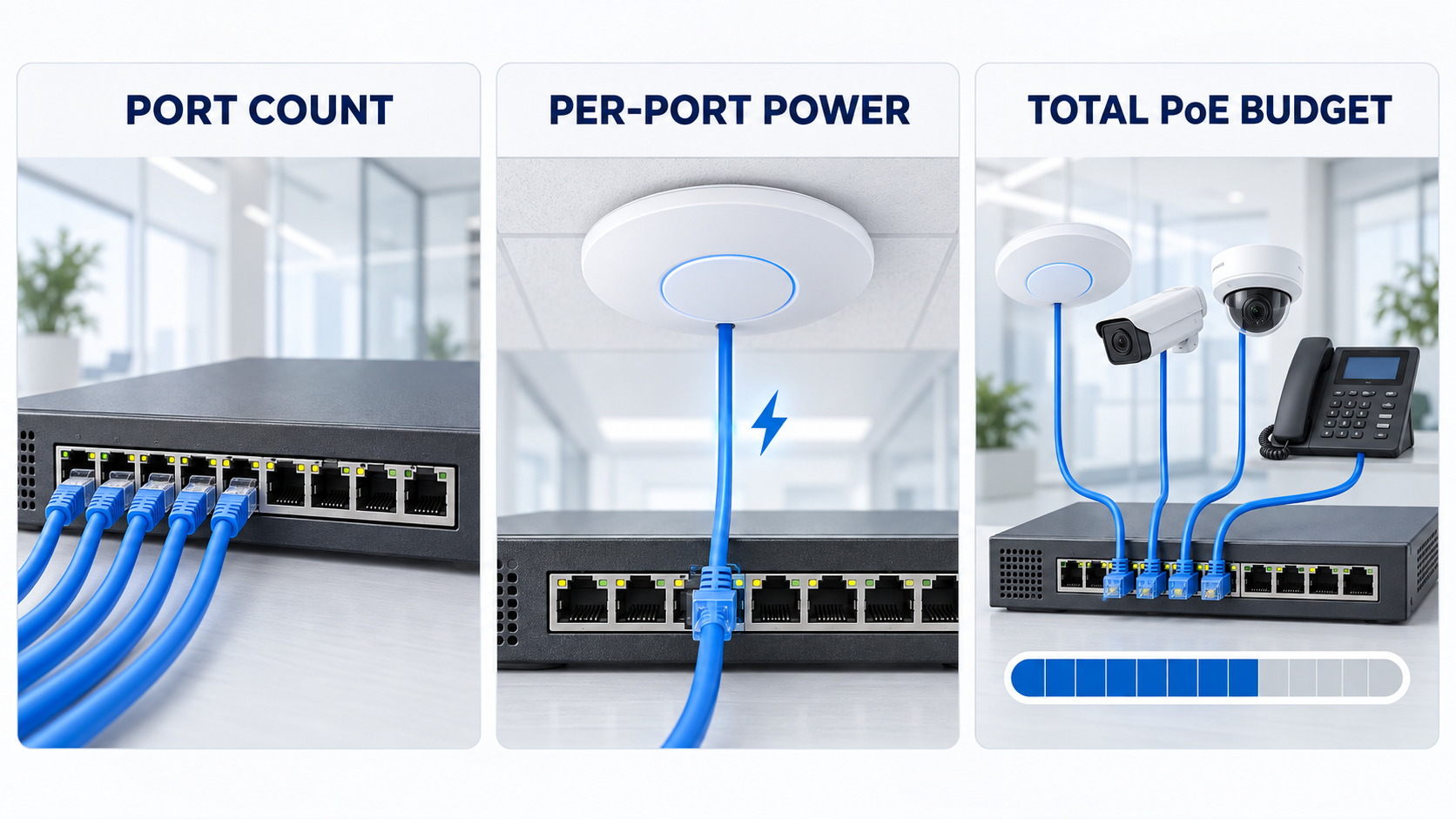
Three Limits Must Pass Independently
A design must fit the available PoE port count, the power limit of every individual port, and the total switch PoE budget. Passing one or two of these checks does not guarantee that the complete design will work.
06 Preserve Reserve Capacity
A switch should not ordinarily be planned to operate at its theoretical PoE limit from the first day. Reserve capacity helps accommodate reasonable variation, device replacement, configuration changes, and limited expansion.
A 20-percent reserve is a useful starting point for many planning exercises, but it is not a universal engineering requirement. The appropriate reserve depends on:
- How accurately maximum device demand is documented
- Whether additional devices are expected
- How difficult the switch would be to replace
- The operational importance of the connected systems
- Whether device models or features may change
- Whether another switch or power source is available
To determine how much of the switch budget remains available after preserving a reserve:
Usable target = Total PoE budget × (1 − Reserve percentage)
For a 120-watt switch with a 20-percent reserve:
120 W × (1 − 0.20) = 96 W usable target
The example’s 97-watt maximum load fits within the switch’s absolute 120-watt budget, but it exceeds the 96-watt planning target by one watt. The switch can support the entered maximum load on paper, but it does not preserve the selected 20-percent reserve.
To calculate the minimum total budget required while preserving a selected reserve:
Recommended PoE budget = Maximum planned load ÷ (1 − Reserve percentage)
For the 97-watt maximum load and a 20-percent reserve:
97 W ÷ 0.80 = 121.25 W
A switch budget above approximately 121 watts would be required mathematically. In practice, the next appropriately sized model—such as a 150-watt-class option—may provide a cleaner margin, subject to its actual port configuration and specifications.
07 Interpret the Result Correctly
The final result should be classified according to both hard limits and the desired planning reserve.
| Result | Meaning | Recommended Response |
|---|---|---|
| Capacity available | Maximum load fits within the budget while preserving the selected reserve | Verify specifications and proceed with normal design review |
| Fits, but reserve is below target | Maximum load fits within the absolute budget but consumes some planned reserve | Review expansion needs, device assumptions, and the next larger switch option |
| Switch does not meet the plan | Total budget, port count, or an individual per-port requirement is exceeded | Select a more appropriate switch, divide the load, or provide another compatible power source |
A result slightly below the desired reserve is not the same as exceeding a hard electrical limit. It signals a planning tradeoff that should be evaluated rather than hidden.
Likewise, unused wattage does not automatically mean the design has adequate expansion capacity. New devices also require available ports, appropriate standards, uplink capacity, switching capacity, cabling, rack space, cooling, and backup power.
08 Account for Real Switch and Device Behavior
The arithmetic is an essential planning step, but real equipment can introduce additional constraints.
Review the following before purchasing or deploying the switch:
- Negotiated power: Devices and switches may allocate or report power differently depending on classification and negotiation.
- Shared power supplies: The available PoE budget may depend on the installed power supply or redundant-power mode.
- Port groups: Some switches provide different capabilities on different groups of ports.
- Ambient temperature: Certain equipment may have reduced operating limits under high-temperature conditions.
- Cable conditions: Cable length, conductor quality, terminations, heat, and installation conditions affect power delivery.
- Powered-device features: Heaters, infrared illumination, motors, radios, USB loads, and accessories can increase demand.
- Power priority: Managed switches may shed lower-priority devices if the available power budget is exceeded.
- Startup behavior: Several devices restarting together may create different conditions from ordinary steady-state operation.
For larger or operationally important systems, review the switch documentation, powered-device specifications, power-supply configuration, and environmental limitations together.
After deployment, compare the actual reported consumption with the planning assumptions. Large differences should be investigated, but low observed consumption alone should not be used to remove all reserve.
09 Use the Free PoE Budget Calculator
The free NaplesTechPro PoE Budget Calculator applies the same planning method described in this guide.
Enter:
- The switch’s documented total PoE budget
- The number of usable PoE-capable ports
- The selected per-port output limit
- The desired reserve percentage
- Each powered-device group and quantity
- Expected and maximum watts per device
The calculator evaluates:
- Total expected load
- Total maximum load
- Unused PoE capacity
- Remaining PoE-capable ports
- Reserved capacity
- Recommended total budget
- Per-port power conflicts
- Whether the plan fits, fits without the desired reserve, or exceeds a hard limit
Calculate Your Planned PoE Load
Use the free PoE Budget Calculator to enter your switch capacity, device quantities, expected consumption, maximum demand, and reserve target. The tool runs locally in your browser and does not upload the entered data.
The calculator is a planning aid—not an engineering guarantee. Confirm the actual device datasheets, switch configuration, cable conditions, power-supply behavior, and environmental requirements before purchasing or deploying equipment.
10 Complete the Final Capacity Review
PoE Switch Power-Budget Checklist
- Record the exact switch model and installed power-supply configuration.
- Use the documented PoE budget rather than the switch’s total AC input rating.
- Count only ports that can provide the required PoE service.
- List every powered device and its quantity.
- Record expected and maximum demand for each device.
- Include optional features that can increase power consumption.
- Calculate total expected and maximum device loads.
- Verify every device against the intended port’s power limit and PoE type.
- Confirm that the device count fits the usable PoE-capable port count.
- Select and document a reasonable reserve target.
- Check power-supply, port-group, temperature, and redundant-power limitations.
- Review cabling, terminations, pathway conditions, and environmental exposure.
- Include the PoE load when planning UPS capacity and runtime.
- Document the completed calculation for future expansion and troubleshooting.
A reliable PoE design makes every limit visible. It distinguishes ordinary consumption from maximum demand, separates per-port capability from total switch capacity, and treats expansion headroom as a deliberate planning decision.
The most important calculation is the total maximum device load, but that number must be reviewed alongside port availability, device compatibility, switch configuration, cabling, environmental conditions, and backup-power requirements.
When those elements are documented together, the switch can be selected for the actual system rather than from port count, marketing labels, or optimistic assumptions.
Start with the device inventory, calculate the expected and maximum loads, preserve an appropriate reserve, and then confirm the result with the NaplesTechPro PoE Budget Calculator.