
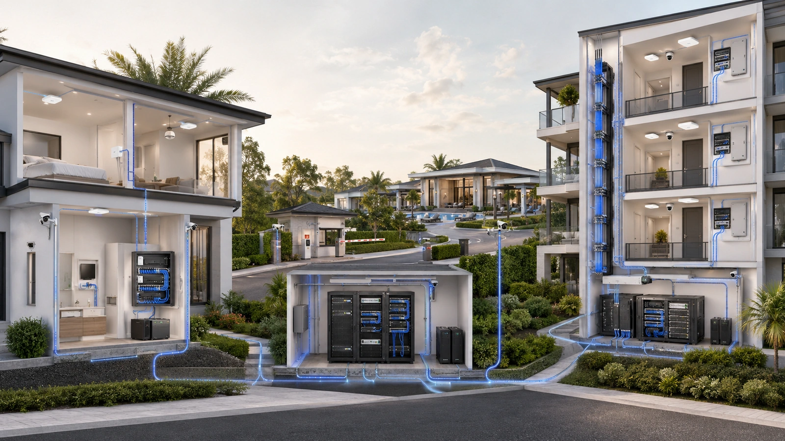
A reliable network is not defined by a particular manufacturer or by the highest number printed on a product box.
Reliability comes from coordinated infrastructure layers: the internet service enters at a known edge, routing and security policies are enforced deliberately, switches distribute connectivity and power, structured cabling creates stable pathways, access points provide designed wireless service, and management systems make the complete environment visible.
Those layers must also be supported physically through appropriate equipment space, electrical capacity, backup power, cooling, organization, documentation, and lifecycle planning.
When the layers are aligned, individual products can evolve without forcing the property to redesign everything around them.
01 Start With Requirements, Not Products
The same general network layers apply to a private home, gated community, clubhouse, condominium, or high-rise building. Their scale and operational requirements are very different.
Before selecting infrastructure, define:
- Property size, construction, buildings, floors, and outdoor areas
- Users, devices, occupancy patterns, and expected growth
- Internet, remote-work, streaming, and cloud-service requirements
- Staff, resident, guest, vendor, and operational-system access
- Cameras, access control, intercoms, automation, and other connected systems
- Critical services and acceptable outage duration
- Security, privacy, management, and documentation expectations
- Existing cabling, fiber, pathways, equipment rooms, and electrical support
- Available operational expertise and support model
- Budget for installation, licensing, maintenance, and eventual replacement
A product can be technically powerful and still be inappropriate if it is difficult for the property to support, lacks necessary interfaces, consumes too much recurring cost, or cannot fit the physical environment.
The architecture should therefore begin with the environment and its consequences—not with a preferred brand ecosystem.
02 Understand the Complete Infrastructure Stack
A practical property network contains several connected layers. Some functions may share one appliance, while larger environments may distribute them across dedicated systems.
| Infrastructure Layer | Primary Responsibility | Planning Considerations |
|---|---|---|
| Internet edge | Receives service from the provider | Service type, demarcation, provider equipment, addressing, diversity, and support |
| Gateway and security | Routes traffic and enforces network policy | Throughput, segmentation, VPN, failover, inspection, licensing, and recovery |
| Switching | Distributes wired connectivity, network segments, and PoE | Ports, power budget, uplinks, topology, monitoring, and expansion |
| Structured cabling | Provides durable physical connectivity | Cable category, fiber, distance, pathways, testing, labeling, and code requirements |
| Wireless access | Provides mobility and radio coverage | Placement, construction, density, interference, capacity, roaming, and backhaul |
| Management and visibility | Supports configuration, monitoring, alerting, records, and lifecycle management | Ownership, cloud dependency, licensing, logging, backups, and support access |
| Physical and power | Protects and supports all active infrastructure | Racks, space, cooling, circuits, UPS, grounding, environment, and serviceability |
A weakness in one layer can limit the entire system. Faster internet does not correct poor Wi-Fi placement. New access points cannot compensate for inadequate switching power. Enterprise equipment cannot overcome damaged or unsuitable cabling.
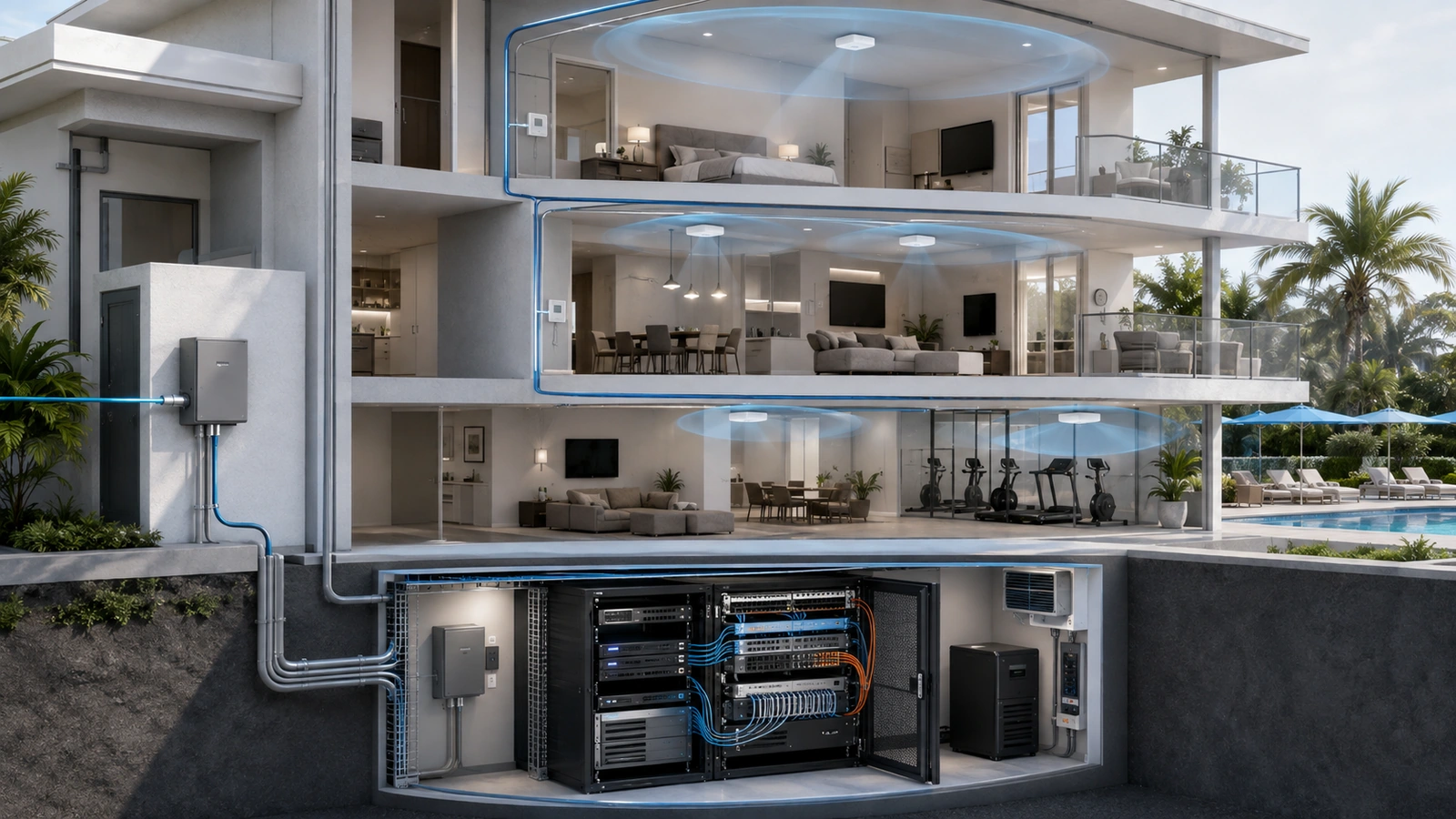
03 Define the Internet Edge and Security Gateway
The internet edge begins where the provider delivers service. Depending on the connection, this may include a modem, optical network terminal, provider gateway, fixed-wireless receiver, or another service handoff.
The property should document:
- Service provider and circuit type
- Demarcation and equipment location
- Property-owned and provider-owned equipment
- Service account and support responsibility
- Addressing and authentication requirements where applicable
- Primary and backup connectivity relationships
- Power supporting the service handoff
Downstream, the gateway routes traffic between networks and toward the internet. Firewall functions enforce allowed communication between different trust zones and external services.
Depending on the design, one appliance may combine routing, firewall, VPN, internet failover, monitoring, wireless control, and limited switching. Larger or more critical environments may separate some of these functions.
Gateway evaluation should consider real throughput with required security and VPN features enabled—not only an advertised maximum under ideal conditions.
Other considerations include supported network segments, policy complexity, connection count, logging, remote administration, configuration backups, licensing, high-availability options, and the property’s ability to support the platform.
04 Build the Switching and Distribution Backbone
Switches connect wired devices and distribute network segments throughout the property. PoE switches may also power access points, cameras, phones, intercoms, access-control components, and other supported devices.
Switch planning should evaluate:
- Total ports and ports reserved for uplinks
- PoE standards required by connected devices
- Total available PoE budget under realistic load
- Uplink and backbone capacity
- Network segmentation and management features
- Environmental and mounting requirements
- Failure impact and replacement strategy
- Monitoring, configuration backup, and support lifecycle
A switch can have open ports while lacking enough available PoE power. It can also support many endpoint connections while relying on an undersized uplink that becomes the actual bottleneck.
A home may use one centrally located managed switch. A community or MDU may require a core layer in the main equipment room and distribution switches in buildings, floors, gatehouses, or amenity locations.
The topology should reflect geography and operational impact. Daisy-chaining switches is not automatically wrong, but every additional dependency should be deliberate, documented, and supported by appropriate uplink capacity and recovery planning.
05 Treat Cabling and Fiber as Long-Life Infrastructure
Active electronics may be replaced several times during the life of a structured cabling system. Pathways and installed cable are therefore among the most important long-term investments.
Cabling design should consider:
- Required data rate and supported channel distance
- PoE requirements and bundle conditions
- Indoor, outdoor, plenum, riser, and environmental ratings
- Building, firestopping, grounding, and code requirements
- Home-run topology and distribution locations
- Fiber between buildings, floors, and high-capacity areas
- Conduit, tray, sleeve, and expansion capacity
- Termination, certification testing, labeling, and records
Category 5e cabling can support standard Gigabit Ethernet when installed within applicable channel requirements. Category 6 or other appropriately selected cabling may provide additional performance or installation advantages depending on distance, application, PoE load, and future plans. “Higher category” alone does not guarantee a compliant or high-performing installation.
Fiber is often appropriate for building-to-building links, vertical backbones, electrically isolated locations, longer distances, and high-capacity uplinks. Fiber type, strand count, pathway, connectors, optics, testing, and future use should be planned together.
Installed cabling should be tested for its intended application and documented—not merely confirmed through a basic continuity light.
06 Design Wi-Fi as an Access Layer
Wireless access points provide radio connectivity. They should be placed according to the building and users they serve, not according to the location of the internet modem or the most convenient electrical outlet.
Wireless design should consider:
- Construction materials and attenuation
- Coverage areas and mounting restrictions
- Expected client density and application demand
- Channel availability and neighboring interference
- Access-point placement, orientation, and transmit power
- Roaming requirements
- Wired backhaul and PoE availability
- Separate staff, resident, guest, vendor, and operational services
- Validation under representative occupancy
Coverage and capacity are different design questions. A user can receive a strong signal from an overloaded access point and still experience poor performance.
Additional access points do not automatically improve Wi-Fi. Poor spacing, uncontrolled channels, excessive transmit power, or wireless backhaul limitations can create interference and inconsistent roaming.
Wired access points are generally preferred where stable cabling is practical. Wireless mesh can be useful where cabling is unavailable or as a deliberate temporary or limited design, but its performance depends heavily on placement, radio conditions, and backhaul quality.
The complete prioritization framework appears in Wired vs Wireless Infrastructure: What Should Be Prioritized First?.
07 Support the Stack With Space and Power
Network equipment needs a physical environment appropriate to its operational role.
A residential structured panel may be suitable for passive terminations and compact equipment, while a deeper wall-mounted rack may better support larger switches, patch panels, gateways, UPS systems, and service access.
Community and MDU equipment spaces should address:
- Secure authorized access
- Rack width, depth, load, and expansion space
- Patch panels and cable management
- Working clearance and serviceability
- Temperature, ventilation, moisture, and dust
- Dedicated electrical capacity where required
- Appropriate grounding and surge protection
- UPS loading, runtime, monitoring, and battery replacement
- Generator or alternate-power relationships where applicable
UPS protection should cover the complete service path required during a short outage. Protecting the gateway alone does not preserve connectivity if the provider handoff, core switch, distribution switch, or access point loses power.
Runtime should be matched to operational requirements. A private home and a gatehouse supporting access or security functions may justify different continuity targets.
Electrical work, grounding, circuits, environmental changes, and code-related requirements should be evaluated and performed by appropriately qualified professionals.
08 Add Management, Monitoring, and Operational Ownership
Infrastructure is easier to operate when authorized teams can see its health, understand its configuration, and identify ownership.
Useful visibility may include:
- Internet circuit and gateway availability
- Switch status, port state, errors, uplinks, and PoE consumption
- Access-point health, channel use, client load, and retry behavior
- Equipment-room temperature and UPS status
- Configuration changes and administrative activity where supported
- Firmware, license, warranty, and support lifecycle
- Alerts connected to an owner and response procedure
Monitoring should create actionable visibility rather than an uncontrolled stream of notifications. Every important alert should have a responsible owner, severity, response expectation, and escalation path.
Cloud management can simplify administration but introduces internet, account, licensing, and vendor-platform dependencies. The property should understand what remains functional and manageable if cloud access is unavailable.
Administrative accounts, documentation, configuration backups, subscriptions, and recovery methods should remain under appropriate property control even when management is delegated to a service provider.
09 Match Role Separation to the Environment
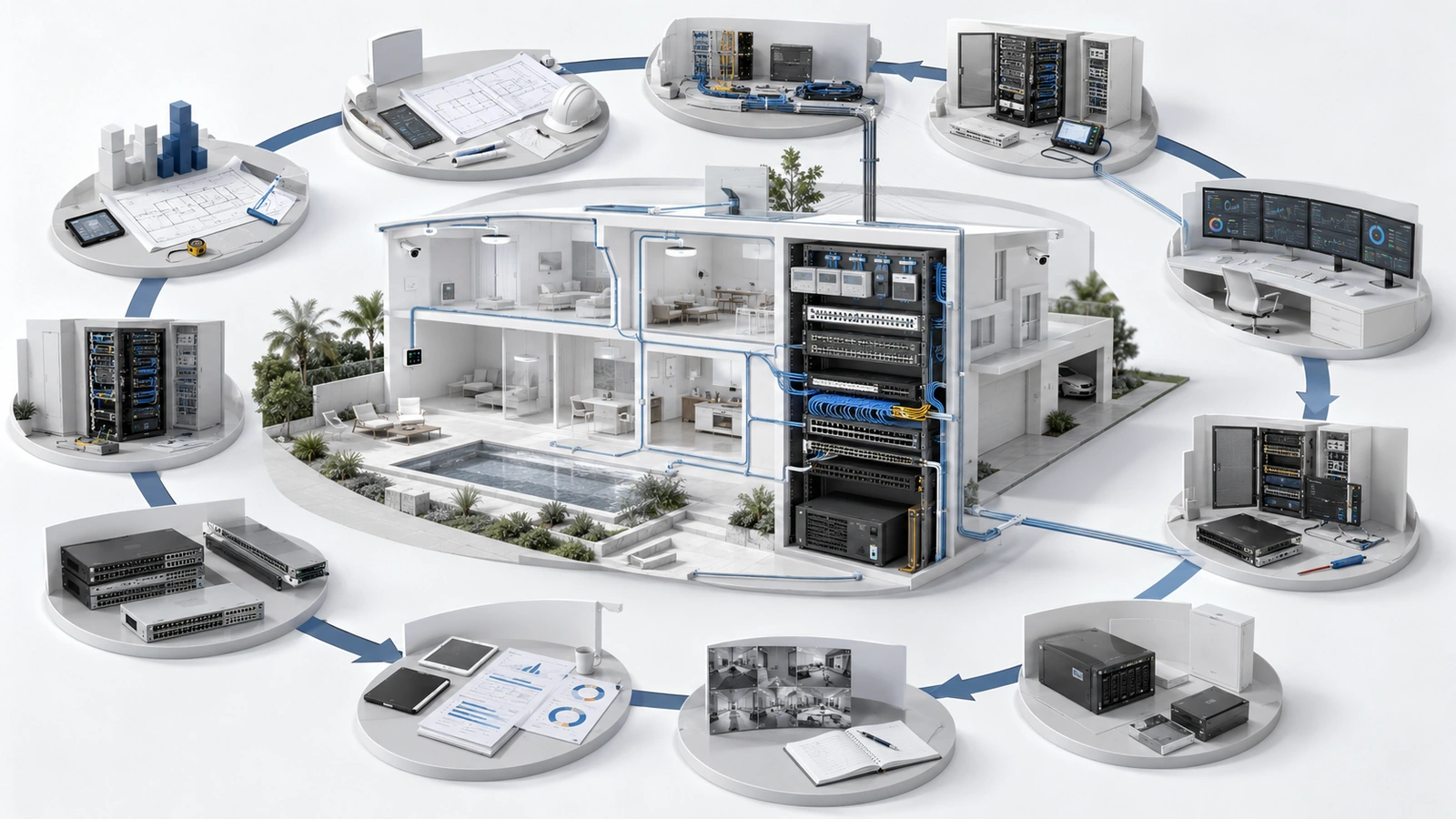
Separating infrastructure roles can improve capacity, placement flexibility, troubleshooting, and replacement options. It does not mean every environment requires a dedicated appliance for every function.
An all-in-one gateway, firewall, switch, controller, and access point may be appropriate for a small residence with modest coverage, limited wired devices, and simple support requirements.
Role separation becomes more valuable when:
- The property requires several access points
- Equipment must be placed in different locations
- PoE demand or wired-device count increases
- Several network segments and security policies are required
- Failure of one appliance would affect too many services
- Performance, monitoring, or lifecycle requirements exceed integrated-device capability
- Independent component replacement provides meaningful operational value
Reliable Network Stack Review Checklist
- Document requirements, users, devices, locations, services, and expected growth.
- Identify the provider handoff, property boundary, and internet-support responsibility.
- Verify gateway throughput with required security, VPN, and failover features enabled.
- Calculate switch ports, PoE demand, uplink capacity, and expansion requirements.
- Confirm that cabling, fiber, pathways, labels, and test records support the design.
- Design Wi-Fi for coverage, capacity, interference, placement, roaming, and wired backhaul.
- Review racks, panels, power, cooling, grounding, UPS load, and serviceability.
- Define monitoring, alert ownership, configuration backup, and administrative recovery.
- Review licensing, cloud dependency, warranties, support status, and replacement planning.
- Separate roles only where the resulting control and flexibility justify the added complexity.
- Preserve practical headroom without purchasing speculative equipment with no defined use.
- Maintain physical and logical documentation as the environment changes.
Equipment selection should follow this architecture. See How to Choose the Right Networking Equipment Without Overspending.
Final Perspective
A reliable network stack is not a fixed list of products. It is a set of coordinated responsibilities.
The internet edge receives service. The gateway and firewall establish routing and trust. Switching distributes connectivity and power. Cabling and fiber create durable paths. Access points provide designed wireless service. Physical infrastructure protects the equipment. Management and monitoring preserve operational visibility.
A small home may combine several of these functions. A community or MDU may distribute them across buildings, floors, equipment rooms, and specialist systems.
The correct design is the one that meets the property’s actual requirements, remains understandable to its operators, preserves reasonable growth options, and can be maintained throughout its lifecycle.
Products will change. A well-structured architecture gives the property a stable foundation on which those future products can operate.