
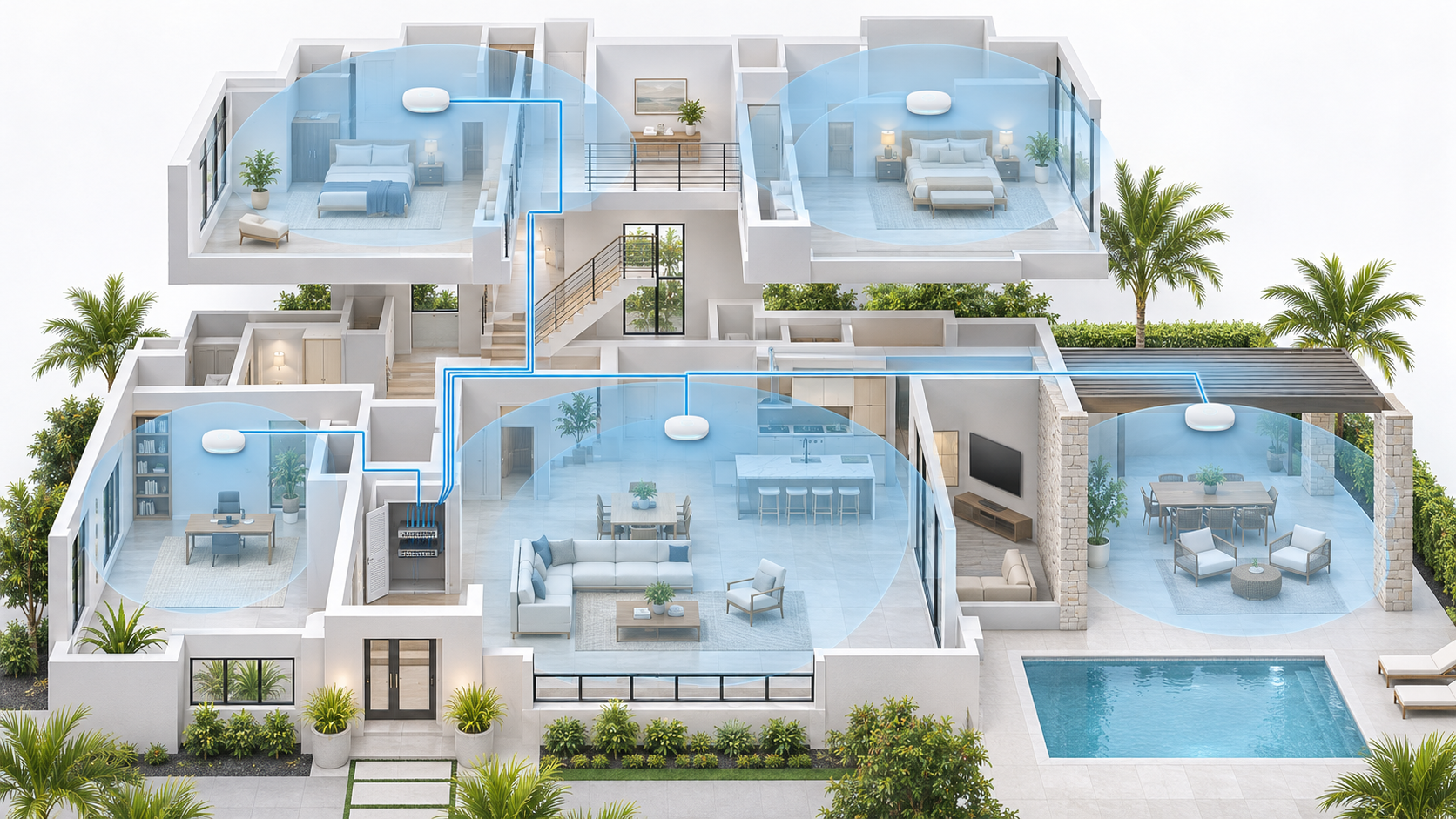
A Wi-Fi coverage plan should explain more than how many access points might be required. It should identify the areas each access point is expected to serve, the construction conditions affecting those areas, the devices and applications creating demand, and the locations where the preliminary design must be tested.
Square footage can provide an initial reference, but it cannot show how concrete walls, separate floors, outdoor spaces, detached buildings, concentrated device activity, or unsuitable mounting locations will affect the finished network.
A more useful method divides the property into meaningful coverage zones and evaluates each zone separately. The resulting access-point range can then be transferred to a floor plan, coordinated with cabling and PoE requirements, and validated through temporary placement or a wireless site survey.
This guide explains that complete process and matches the assumptions used by the free NaplesTechPro Wi-Fi Coverage Planner.
Key Takeaway
Divide the property into logical Wi-Fi zones, estimate each zone according to its area, construction, usage, and active-device demand, and use the larger of the coverage-led or capacity-led requirements. Treat the result as a preliminary planning range—not a final RF design or permission to distribute access points evenly by square footage.
01 Define What the Wi-Fi Must Accomplish
Begin with the experience the wireless network must provide. A property requiring basic browsing and smart-device connectivity may need a different design from one supporting video conferences, Wi-Fi calling, wireless point-of-sale devices, streaming, security equipment, or crowded shared spaces.
Document the areas where Wi-Fi is:
- Operationally essential
- Required for work or communication
- Expected for residents, employees, or guests
- Needed by fixed smart or security devices
- Helpful but not critical
- Outside the intended project scope
This distinction prevents the design from treating every square foot as though it requires identical performance.
A home office used for daily video meetings deserves more deliberate coverage than a storage room. A restaurant’s ordering and payment areas deserve different consideration from a lightly used hallway. A patio used for events may require more than an accidental signal passing through an exterior wall.
Also define whether the project is intended to provide ordinary connectivity, dependable voice and video performance, concentrated device capacity, outdoor service, or continuous roaming between important areas. These objectives influence the access-point quantity, placement, channel design, and validation method.
02 Start With an Accurate Floor Plan
An accurate floor plan makes the preliminary coverage estimate considerably more useful. It reveals the shape of the property, distances between important rooms, separate wings, floor transitions, exterior boundaries, and possible access-point locations.
Mark the following information when available:
- Exterior dimensions and total planned area
- Interior walls and major room divisions
- Concrete, masonry, metal, glass, tile, and other dense materials
- Floor assemblies between levels
- Elevator shafts, mechanical rooms, and large equipment
- Network closets, structured wiring panels, and equipment rooms
- Existing and proposed Ethernet pathways
- Ceiling heights and practical mounting surfaces
- Patios, pools, garages, docks, and detached buildings
- Areas with important fixed wireless devices
The floor plan does not need to become a complete predictive RF model during early planning. Its first purpose is to prevent the estimate from becoming one undifferentiated square-footage calculation.
If an accurate drawing is unavailable, create a basic measured sketch and verify the major dimensions during an on-site walkthrough.
03 Divide the Property Into Meaningful Coverage Zones
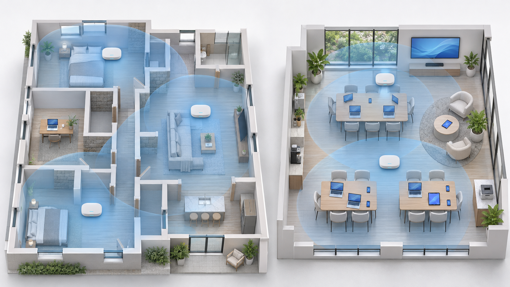
A coverage zone is an area that can reasonably be evaluated as one wireless service responsibility. It may contain several adjacent rooms when the layout is open, or only one room when dense barriers isolate it from the surrounding property.
Common residential zones include:
- Main kitchen and living area
- Primary bedroom wing
- Separate bedroom or guest wing
- Upper floor
- Home office or media room
- Garage or workshop
- Lanai, pool, or outdoor kitchen
- Detached guesthouse or accessory building
Small-business and hospitality zones may include:
- Public or customer-facing areas
- Private offices and conference rooms
- Operational or point-of-sale areas
- Dining rooms and event spaces
- Kitchens, service areas, or storage spaces
- Outdoor seating or recreational areas
- Warehouses, workshops, or separated buildings
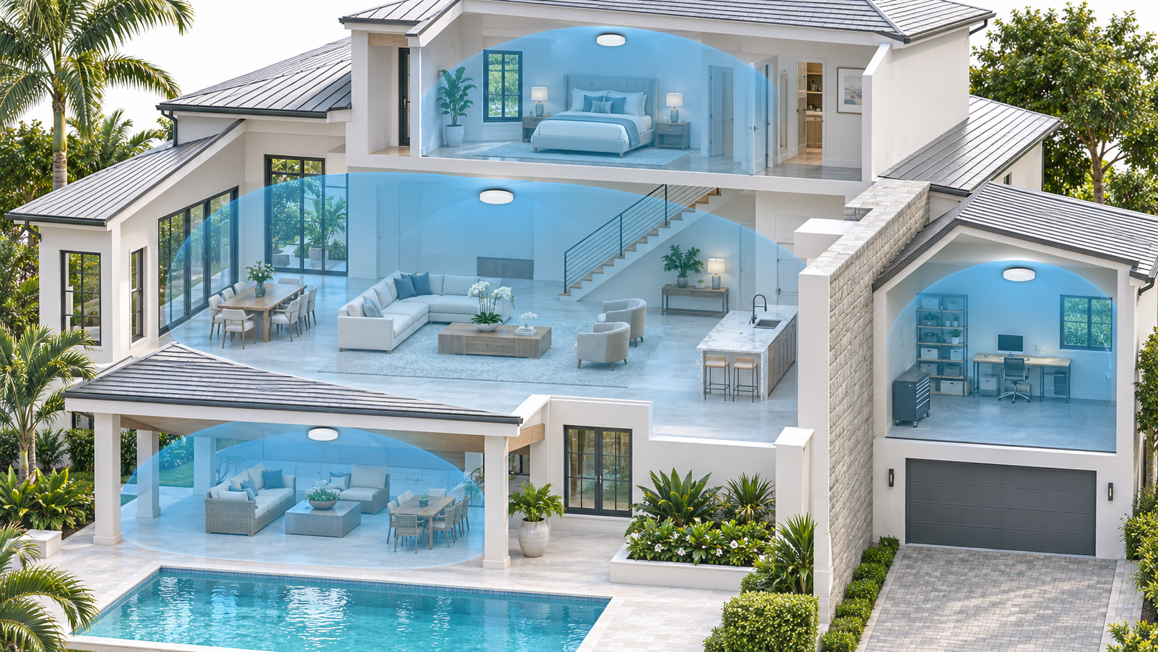
Each floor should normally be reviewed separately, but that does not mean every floor automatically receives exactly one access point. Coverage may travel between levels, and one large or divided floor may require several service zones.
Detached buildings and materially isolated spaces should remain separate zones even when their square footage is small. They also require a dependable wired, fiber, or properly designed wireless backhaul to the main network.
04 Classify the Environment of Each Zone
Construction and layout influence how much area one access point can serve effectively. The Wi-Fi Coverage Planner uses five practical environment classifications.
| Environment | Typical Conditions | Planning Response |
|---|---|---|
| Open / light partitions | Open rooms with relatively few major obstructions | Allows the largest preliminary area allowance |
| Typical mixed walls | Ordinary rooms with conventional interior partitions | Uses the standard planning baseline |
| Dense masonry / concrete | Concrete, block, masonry, metal, tile, or several dense barriers | Uses a substantially smaller area allowance |
| Outdoor open area | Patio, pool, courtyard, or another relatively open exterior space | Evaluated separately with outdoor installation requirements |
| Detached / isolated area | Separate structure or space divided by a major boundary | Treated as its own coverage cell with a separate backhaul check |
These classifications are planning categories—not guarantees about RF propagation. A single material label cannot describe every wall assembly, and several moderate obstacles may collectively create more loss than one obvious barrier.
Concrete-block construction is particularly relevant in Florida properties. An indoor access point may perform well throughout the interior while providing inconsistent service to a lanai, pool, driveway, doorbell, or exterior camera through the building envelope.
When dependable service is required on both sides of a major barrier, plan coverage on both sides instead of assuming that increased transmit power will solve the problem.
05 Select the Primary Design Band
The NaplesTechPro planner provides two preliminary design-band options:
- 5 GHz: The recommended baseline for most balanced home and small-business plans.
- 6 GHz: A denser planning option for compatible devices and shorter service distances.
The selected design band does not mean the finished network must operate only on that band. Modern access points may support 2.4, 5, and 6 GHz simultaneously, and many properties continue to rely on more than one band because their client devices and service requirements differ.
A 6 GHz-first objective generally requires more deliberate placement and validation. Client compatibility, wall penetration, transmit-power rules, mounting, channel planning, and dependable 5 GHz fallback must all be confirmed.
The planner therefore reduces its preliminary area allowance when 6 GHz is selected. This is a conservative planning adjustment—not a universal formula predicting the finished signal level of every access point.
The Design Band Changes the Planning Assumption
Selecting 6 GHz should not be treated as a simple equipment upgrade. It changes the coverage objective and requires verification with compatible client devices, appropriate access points, a floor plan, and site-specific testing.
06 Calculate the Coverage-Led Minimum
The coverage-led estimate asks how many access points may be needed to serve the physical area and construction conditions of each zone.
The planner begins with these baseline allowances:
| Property Type | 5 GHz Mixed-Wall Baseline | Planning Use |
|---|---|---|
| Residential | 1,200 ft² per AP | Preliminary home-planning baseline |
| Small business / hospitality | 1,000 ft² per AP | More conservative operational baseline |
The baseline is adjusted according to the zone environment and selected design band:
Zone area allowance = Property baseline × Environment factor × Design-band factor
The coverage-led minimum is then:
Coverage-led AP minimum = Zone area ÷ Adjusted area allowance, rounded up
For a 1,700-square-foot residential zone with typical mixed walls and a 5 GHz design baseline:
1,700 ft² ÷ 1,200 ft² per AP = 1.42
Because a fraction of an access point cannot serve the remaining area, the preliminary coverage-led minimum rounds up to two access points.
The planner uses intentionally more conservative allowances for dense construction and 6 GHz-first planning. These allowances are NaplesTechPro planning assumptions—not manufacturer specifications, code requirements, or guaranteed coverage limits.
07 Calculate the Capacity-Led Minimum
Coverage and capacity are different planning questions. A zone may have excellent signal but still contain more simultaneous activity than the intended design should place on one access point.
Estimate the number of devices expected to be active during a busy but realistic period. Do not automatically enter every device that exists on the property. A powered smart device that sends occasional small updates does not create the same demand as a laptop in a video conference or a television streaming high-resolution content.
The planner uses the following preliminary active-device limits:
| Usage Profile | Planning Limit | Typical Activity |
|---|---|---|
| Light browsing / IoT | 45 active devices per AP | Light browsing, sensors, and low-demand smart devices |
| Mixed everyday use | 35 active devices per AP | General browsing, applications, streaming, and mobile use |
| Video calls / streaming | 25 active devices per AP | Real-time communication and sustained media activity |
| High-density shared use | 20 active devices per AP | Concentrated simultaneous demand in shared areas |
The capacity-led calculation is:
Adjusted active devices = Peak active devices × (1 + Planning reserve)
Capacity-led AP minimum = Adjusted active devices ÷ Usage limit, rounded up
For 28 active devices under the mixed everyday-use profile with a 10-percent reserve:
28 × 1.10 = 30.8 adjusted active devices
30.8 ÷ 35 devices per AP = 0.88
The preliminary capacity-led minimum rounds up to one access point. However, the same zone’s coverage calculation may still require two.
The device limits are intentionally simplified planning assumptions. Actual capacity depends on application traffic, airtime use, channel width, channel reuse, interference, client capabilities, access-point model, radio configuration, and the performance level the project must maintain.
08 Use the Larger Requirement for Each Zone
For each coverage zone, compare the coverage-led minimum with the capacity-led minimum:
Preliminary zone requirement = Larger of coverage minimum or capacity minimum
If coverage requires two access points and capacity requires one, the preliminary zone requirement is two. If coverage requires one but concentrated activity requires two, the zone becomes capacity-led.
| Zone Condition | Primary Driver | Planning Meaning |
|---|---|---|
| Large or obstructed area | Coverage | Physical reach and construction create the larger requirement |
| Small but busy shared area | Capacity | Concentrated active-device demand creates the larger requirement |
| Large and heavily used area | Coverage and capacity | Both calculations may produce the same requirement |
Adding access points to a capacity-led zone only helps when the radios, channels, transmit power, wired uplinks, and distribution of client devices are coordinated correctly. Placing several access points close together without a channel and power plan may increase interference instead of usable capacity.
The individual zone requirements are added to establish the lower end of the property-wide planning range.
The planner produces the upper end by adding approximately 20 percent, with at least one additional access point. This upper value provides a review range for isolation, unexpected interference, difficult construction, or greater 6 GHz continuity.
The upper result is not an instruction to purchase every access point in the range. Begin floor-plan placement with the lower number and move upward only when the zone layout and validation findings justify it.
09 Apply the Method to a Practical Example
Consider a two-story 4,200-square-foot coastal home with a lanai and a garage separated by dense construction. The plan uses 5 GHz as its primary design band and applies a 10-percent capacity reserve.
| Coverage Zone | Zone Inputs | Preliminary Requirement |
|---|---|---|
| First floor | 1,700 ft², mixed walls, 28 active devices | 2 APs, driven by coverage |
| Second floor | 1,100 ft², mixed walls, 18 real-time devices | 1 AP |
| Lanai / pool area | 900 ft², outdoor area, 12 active devices | 1 AP |
| Garage | 500 ft², dense separation, 6 light-use devices | 1 AP |
| Complete property | 4,200 ft² and 64 peak active devices | 5–6 AP planning range |
The example produces a coverage-led total of five access points and a capacity-led total of four. The lower planning result is therefore five because the individual zones are primarily limited by their physical coverage responsibilities.
The upper end becomes six access points after applying the planner’s review allowance.
This does not mean the property should automatically receive six devices. The five-access-point plan should first be placed on the floor plan. Temporary testing may show that one access point can serve two adjacent zones, or that a difficult boundary requires the sixth device.
The lanai and garage also introduce requirements beyond quantity. The outdoor area needs suitable equipment and installation, while the isolated garage requires confirmation that Ethernet, fiber, or another reliable backhaul can reach it.
10 Convert the Quantity Into Proposed Locations
An access-point count becomes useful only after every device has a defined coverage responsibility and a realistic mounting location.
For each proposed access point, document:
- The zone or rooms it is intended to serve
- The expected mounting type and orientation
- The walls, floors, or exterior boundaries along important signal paths
- The location of high-priority client devices
- The availability of Ethernet and PoE
- The expected overlap with neighboring access points
- Whether outdoor exposure or special installation requirements apply
- Whether the position remains accessible for service and replacement
Do not distribute access points evenly across the drawing merely because the preliminary result contains a certain number. Architecture, usage, mounting orientation, and cabling should determine the locations.
One unit may belong near the center of a main living zone, another toward a bedroom wing, and another on an upper floor positioned away from the first-floor unit. An outdoor access point may need to sit near the occupied patio rather than at the geometric center of the property.
For detailed placement guidance, see How to Place Wi-Fi Access Points: A Home Placement Blueprint.
11 Confirm Backhaul, Switching, and Power
Every proposed access-point location needs a dependable path to the network. The planner assumes wired backhaul because Ethernet normally provides the most predictable connection and avoids using wireless airtime for the upstream link.
For every proposed location, confirm:
- An appropriate Ethernet pathway
- The cable category and distance
- The patch-panel and switch-port assignment
- The required PoE standard
- The access point’s expected and maximum power demand
- Available switch PoE capacity and reserve
- Surge, grounding, and exterior-cabling considerations where applicable
- A serviceable mounting and cable-termination method
If the design uses wireless mesh or another wireless backhaul, evaluate the quality of the upstream connection separately. A mesh access point cannot provide dependable service merely because client devices can see its signal. It must also maintain a strong and stable path to the upstream network.
Use the PoE switch power-budget guide when several access points or other PoE devices will share the same switch.
12 Validate the Preliminary Plan
A zone-based estimate is more useful than a universal square-footage rule, but it remains a preliminary plan. The final design must account for actual RF behavior at the property.
Validation may include:
- A physical walkthrough
- Review of accurate floor plans and construction information
- Predictive modeling using the intended access-point model
- Temporary access-point placement before permanent installation
- Passive and active wireless surveys
- Post-installation coverage and application testing
- Review of interference, channel use, transmit power, and access-point load
Test the areas and applications that matter—not only the signal directly underneath an access point. Walk through offices, bedrooms, outdoor areas, floor transitions, closed-door conditions, and roaming paths.
Validation should consider:
- Signal strength and signal-to-noise conditions
- Upload and download performance
- Latency, retransmissions, and packet loss
- Video calls and Wi-Fi calling
- Roaming between service areas
- Behavior of ordinary client devices
- Performance during representative busy periods
- Operation of fixed smart, security, and business devices
A predictive plan is especially helpful before construction or cabling is complete. An active survey and post-installation validation provide additional evidence about how the selected equipment and real client devices perform in the finished environment.
Do Not Validate With One Speed Test
A successful test directly underneath an access point does not confirm coverage throughout the property. Validate the intended applications at zone boundaries, behind important barriers, across floors, outdoors, and along expected roaming paths.
13 Use the Free Wi-Fi Coverage Planner
The free NaplesTechPro Wi-Fi Coverage Planner applies the preliminary workflow described in this guide.
Enter:
- The property type
- The primary 5 GHz or 6 GHz design band
- The selected capacity reserve
- Each coverage zone and its area
- The environment of each zone
- The expected usage profile
- The peak number of active devices
- Optional project notes
The planner calculates:
- The total planned area
- The peak active-device count
- The coverage-led minimum
- The capacity-led minimum
- The preliminary requirement for each zone
- The complete access-point planning range
- Warnings for dense construction, outdoor areas, isolated spaces, 6 GHz planning, and capacity-led zones
Build Your Preliminary Coverage Plan
Use the free Wi-Fi Coverage Planner to divide the property into meaningful zones and compare coverage-led and capacity-led access-point requirements. The tool runs locally in your browser and does not upload the information you enter.
The resulting range is a planning estimate—not a predictive RF design, site survey, engineering certification, or performance guarantee. Actual results depend on the access-point model, mounting, antenna pattern, transmit power, channel design, interference, client devices, building materials, backhaul, and configuration.
14 Complete the Final Coverage Review
Wi-Fi Coverage Planning Checklist
- Define the applications and service experience the Wi-Fi must support.
- Identify essential, secondary, and out-of-scope coverage areas.
- Obtain or create an accurate floor plan.
- Mark floors, wings, outdoor areas, and detached structures.
- Identify concrete, masonry, metal, glass, and other major barriers.
- Divide the property into meaningful coverage zones.
- Select the primary planning band.
- Estimate peak active devices for every zone.
- Select the usage profile that best represents each zone.
- Apply an appropriate capacity reserve.
- Compare the coverage-led and capacity-led requirements.
- Use the larger requirement for each zone.
- Assign a clear coverage responsibility to every proposed access point.
- Confirm mounting type, orientation, and service access.
- Confirm Ethernet or another dependable backhaul.
- Verify switch ports, PoE standards, and available power capacity.
- Use suitable equipment and installation practices outdoors.
- Review channel use, transmit power, and expected overlap.
- Temporarily test uncertain locations whenever practical.
- Validate the installed design throughout all important areas.
- Document the final locations, cabling, switch ports, and configuration.
- Reassess the plan after layout, usage, or equipment changes.
A dependable Wi-Fi plan connects the property’s layout, construction, usage, active-device demand, access-point locations, cabling, power, and validation process. It does not rely on one advertised coverage number or assume that every area of equal size behaves the same way.
Begin with the required experience, divide the property into logical zones, and compare the physical coverage requirement with the active-device capacity requirement. Then place the resulting access points deliberately on the floor plan and verify the design under real conditions.
Use the NaplesTechPro Wi-Fi Coverage Planner to organize those assumptions and create a preliminary access-point range before equipment is purchased or permanent cabling and mounting decisions are finalized.