
Introduction
A capable wireless access point can perform poorly when it is installed in the wrong location. Put it inside a metal panel, behind a television, at the far end of the home, or in an orientation it was not designed for, and even excellent hardware begins with a disadvantage.
Effective placement is not simply about finding the geometric center of the property. Each access point should be positioned according to the area it must serve, the materials around it, the direction in which it radiates, and the neighboring access points with which it shares the wireless environment.
The goal is neither maximum signal everywhere nor perfectly equal spacing between devices. The goal is deliberate coverage: dependable connections in important rooms, sensible overlap between service areas, and as little unnecessary interference as practical.
01 Placement Begins With a Coverage Plan
Before choosing exact mounting points, identify the areas that require dependable Wi-Fi. A floor plan is extremely useful, but it should be interpreted according to how the home is actually used.
Mark the locations of:
- Main living and kitchen areas
- Bedrooms and separate residential wings
- Home offices and study areas
- Media rooms and entertainment spaces
- Garages, workshops, and utility areas
- Patios, pools, outdoor kitchens, and lanais
- Doorbells, locks, cameras, and other fixed wireless devices
- Paths where Wi-Fi calling or other roaming-sensitive activity matters
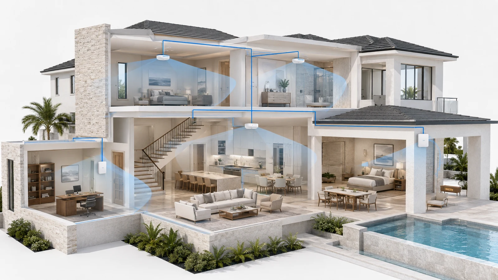
These locations form the home’s coverage zones. One access point may serve several adjacent spaces in an open plan, while a divided wing or dense barrier may require a separate source of coverage.
Placement and access-point count must be planned together. If the initial zones suggest more or fewer devices than expected, use the guide to estimating how many Wi-Fi access points a home needs before purchasing the hardware.
For larger properties, the access points should also be coordinated with the gateway, PoE switch, network location, and wired backbone. That complete relationship is covered in the large-home Wi-Fi blueprint.
02 Respect the Access Point’s Intended Orientation
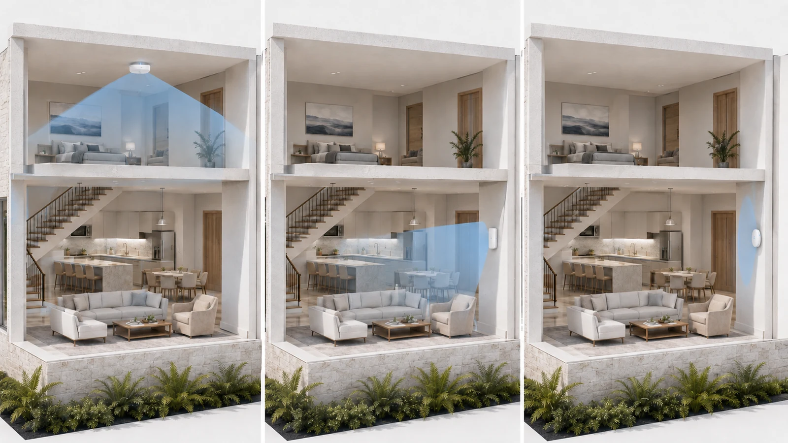
Access points are not interchangeable shapes with identical signal behavior. Ceiling-mounted, wall-mounted, in-wall, desktop, and outdoor models may be designed to serve different environments.
A ceiling-oriented access point commonly directs useful coverage outward and downward from its installed position. Mounting that same device vertically on a wall may rotate its coverage pattern and change which rooms receive the strongest service. A purpose-built in-wall model, by contrast, may be well suited to serving the room in front of it and nearby client devices.
Before selecting a location:
- Confirm the manufacturer’s recommended mounting orientation.
- Review the model’s published radiation-pattern information when available.
- Consider whether the access point is intended for broad-area or targeted coverage.
- Avoid assuming that a visually convenient mounting position is electrically equivalent to the intended one.
Ceiling mounting is often effective in residential installations because it places equipment above furniture and many everyday obstructions. It is not mandatory for every model or room. A properly selected wall or in-wall access point can be the better solution when cabling, architecture, or a targeted usage area makes ceiling mounting impractical.
03 Place the Access Point Within the Zone It Serves
A useful starting point is to position an access point near the center of its intended coverage zone. This reduces the distance to surrounding rooms and avoids spending much of the signal on areas outside the zone.
“Central” does not necessarily mean the center of the entire house. An access point assigned to a bedroom wing should be centered relative to that wing. One intended to serve a covered lanai may appropriately sit near the building’s edge or outdoors. Purpose determines position.
Avoid locations that unnecessarily obstruct or distort the connection, including:
- Inside metal structured wiring panels
- Inside enclosed cabinets or crowded closets
- Behind televisions, appliances, or large mirrors
- Beside ductwork, mechanical equipment, or dense electronics
- On the floor behind furniture
- Deep inside architectural niches
- At an exterior corner when the intended zone is primarily indoors
Ordinary drywall is less problematic than concrete or metal, but every additional obstruction reduces the quality of the path. Whenever possible, give the access point a relatively open position with a short, uncomplicated route to the rooms it must serve.
Hiding wireless equipment may improve the appearance of a room, but concealment should not defeat the purpose of installing it. Small, cleanly mounted access points are usually less intrusive than an unreliable network supplemented later by additional hardware.
04 Account for Walls, Floors, and Residential Construction
Floor plans show room boundaries, but they do not always reveal what those boundaries contain. Concrete, masonry, tile, metal, mirrors, appliances, plumbing, and mechanical systems can change how well an access point serves the space beyond them.
In Naples and throughout Florida, concrete block exterior construction deserves particular attention. An indoor access point may provide excellent interior coverage while struggling to reach a camera, doorbell, patio, or pool area through the building envelope. Impact-resistant assemblies, coated glass, and other exterior materials can add further loss.
Interior obstacles can be equally important when several appear together. A signal path crossing a tiled bathroom, mirror, plumbing wall, and mechanical closet may behave differently from a path of similar length through open rooms and conventional drywall.
| Placement Condition | Likely Effect | Better Planning Response |
|---|---|---|
| Open living area | Fewer major obstructions between the access point and clients | Use a central, unobstructed location that also considers adjacent rooms |
| Concrete or masonry boundary | Signal may decline significantly across the barrier | Place coverage on the side where reliable service is required instead of relying on increased power |
| Mechanical or electronics cluster | Metal, equipment, and dense cabling may obstruct or reflect signals | Move the access point into a clearer adjacent location |
| Exterior wall near patio or pool | Indoor coverage may not transfer consistently outdoors | Evaluate the outdoor space as a separate zone and use suitable equipment when necessary |
| Vaulted or unusually high ceiling | Distance and geometry may reduce service at the occupied level | Avoid defaulting to the highest peak; choose an accessible position suited to the coverage pattern |
| Cabinet or structured panel | The enclosure may restrict signal and trap heat | Keep routing and switching inside when appropriate, but install the access point in an open service area |
The best location may therefore differ from the cleanest point on an architectural drawing. Access to Ethernet, aesthetic concerns, and serviceability matter, but they must be balanced against the wireless path.
05 Plan Multiple Floors as One Connected Environment
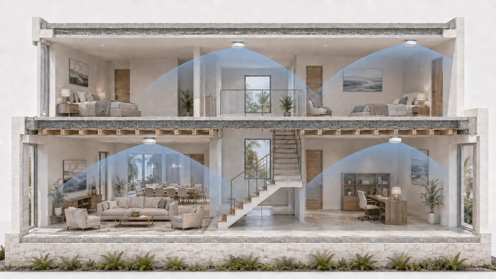
Wi-Fi can travel between floors, but vertical coverage is rarely uniform. Floor assemblies, tile, plumbing, ductwork, furniture, and the access point’s orientation all influence what reaches the level above or below.
Do not assume that every floor automatically requires exactly one access point. A compact two-story home may be served effectively by two well-placed units, while a larger floor with separate wings may need more than one. Conversely, useful vertical coverage may reduce the need for another access point in a small adjacent area.
Access points should not automatically be stacked directly above one another. Vertical alignment may concentrate overlapping coverage in one section of the home while leaving rooms at the opposite ends underserved. Staggered placement often distributes coverage more effectively.
A multi-floor plan might place:
- One downstairs access point near the kitchen and primary living area
- Another downstairs unit toward an office or guest wing
- An upstairs access point positioned toward the bedroom side not already served well from below
Open staircases, atriums, and double-height rooms can allow more signal to travel vertically than expected. That may be helpful, but it can also increase overlap between access points. Treat these openings as part of the design rather than assuming they are either automatically beneficial or harmful.
06 Adapt Placement to the Shape of the Home
Access points cannot reliably “bend” coverage around every corner. Long and irregular homes should be divided according to their geometry.
Long single-story homes: Position access points along the length of the occupied areas, assigning each one a clear section. Do not rely on one powerful access point at the midpoint if several walls and distant end rooms separate the clients from it.
L-shaped homes: Treat each leg as a potential zone. An access point near the intersection may contribute to both areas, but it may not replace coverage farther along each wing.
U-shaped homes: Evaluate the wings separately, especially when exterior walls and an open courtyard stand between them. A signal crossing outdoor space and re-entering the opposite wing may not provide the stable indoor service the floor plan seems to suggest.
Homes with additions: Former exterior walls often remain between the original structure and the addition. These boundaries may be much denser than ordinary interior partitions and should be treated accordingly.
Detached structures: A guesthouse, workshop, or detached garage requires both a coverage plan and a backhaul plan. Adding an access point inside the separate building does not help unless it also has a dependable connection to the primary network.
Architecture should determine the pattern. Equal spacing looks orderly on paper but may place access points in rooms that do not need them while leaving high-value spaces behind difficult barriers.
07 Give Priority Areas Deliberate Coverage
Not every room requires the same wireless performance. Placement should reflect which areas carry the most important or demanding activity.
Home offices: Give workspaces a short, reliable signal path, particularly when video conferencing and Wi-Fi calling are important. Use Ethernet for fixed computers and docks when practical, but still provide strong wireless service for phones, tablets, and visitors.
Media rooms: Wire televisions, streaming devices, game consoles, and AV equipment where possible. Position the access point away from the dense electronics cluster rather than behind the display or inside the AV cabinet.
Bedrooms: Consider closed doors, hallway geometry, and the position of the bed or work area. An upstairs hallway can be effective, but only if it provides a reasonable path into the rooms it is expected to serve.
Garages and workshops: Concrete walls, metal doors, vehicles, and exterior positioning can make garage coverage inconsistent. Decide whether the goal is casual phone access, dependable smart-device connectivity, or service extending into the driveway.
Smart-home and security devices: Doorbells, locks, cameras, irrigation controllers, and exterior sensors often sit at the edges of indoor coverage. Their fixed positions cannot move closer to the network, so validate them individually.
Place infrastructure according to the experience the home needs—not simply where the installer can reach the ceiling most easily.
08 Treat Outdoor Coverage as Its Own Design Problem
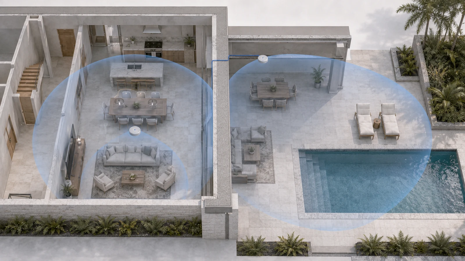
Patios, pools, outdoor kitchens, docks, and driveways should not be treated as accidental extensions of indoor Wi-Fi. An indoor access point near a window may serve a small exterior area, but that result depends on the glass, wall construction, mounting position, and direction of coverage.
When outdoor connectivity is important:
- Identify the actual occupied area rather than attempting to cover the entire property.
- Use an outdoor-rated access point when equipment will be exposed to exterior conditions.
- Select a position protected and permitted according to the equipment’s installation requirements.
- Avoid placing the unit where landscaping, metal structures, outdoor appliances, or building corners obstruct the intended area.
- Confirm an appropriate Ethernet, fiber, or designed wireless backhaul.
- Consider lightning, grounding, surge protection, and local installation requirements for exterior cabling.
Outdoor coverage can also extend farther than intended because it encounters fewer interior walls. Radio settings should be adjusted so the access point serves the required space without creating unnecessary overlap with indoor radios or neighboring properties.
09 Validate Placement Before and After Installation
A floor plan produces an informed preliminary design, not a guarantee. Whenever practical, test proposed locations before making permanent penetrations or finishing cable work.
Temporary testing can reveal:
- A wall that attenuates more signal than expected
- A hallway position that does not reach into closed bedrooms
- Excessive overlap between floors
- An outdoor area isolated by the exterior construction
- A client device that remains attached to a distant access point
- A mesh location without adequate upstream connectivity
After installation, evaluate the network in the places where it matters. Do not validate the entire system with one speed test directly underneath an access point.
Access-Point Placement Checklist
- Define the exact coverage responsibility of every proposed access point.
- Confirm that the model is mounted in its intended orientation.
- Keep the unit outside cabinets, metal panels, equipment clusters, and dense obstructions.
- Position it within the zone it must serve rather than at an arbitrary building center.
- Review concrete, masonry, tile, mirrors, mechanical spaces, and floor assemblies along important signal paths.
- Plan multiple floors together and avoid automatic vertical stacking.
- Account for open staircases, atriums, vaulted ceilings, and double-height spaces.
- Give offices, media rooms, bedrooms, and fixed smart devices deliberate consideration.
- Evaluate garages, patios, pools, and detached structures as separate requirements.
- Confirm Ethernet or a dependable alternative backhaul at every location.
- Check that neighboring access points provide useful but not excessive overlap.
- Test important rooms, property edges, and roaming paths after installation.
Coverage observations should be considered together with channel use, transmit power, client behavior, and backhaul performance. A placement problem cannot always be corrected through configuration, and a configuration problem does not always require moving the hardware.
That distinction is especially important with wireless mesh. A mesh node must be positioned where it can both receive a strong upstream connection and serve its intended clients. The guide to mesh versus wired backhaul explains how that requirement changes placement freedom.
10 Final Placement Blueprint
The strongest access-point placement plans begin with the building rather than the hardware. They identify important usage zones, respect construction barriers, use the correct device orientation, and provide every access point with a dependable network path.
There is no universal mounting height, spacing distance, or one-device-per-floor rule that applies to every home. Those shortcuts can be useful starting assumptions, but they cannot replace the floor plan, the intended coverage pattern, and real-world validation.
Place access points where they can serve the rooms that matter. Keep them clear of avoidable obstructions. Coordinate their coverage across floors and wings. Treat outdoor areas separately. Then test the result from the perspective of the devices and people who will use it.
Good hardware matters, but placement determines whether that hardware can do its job.